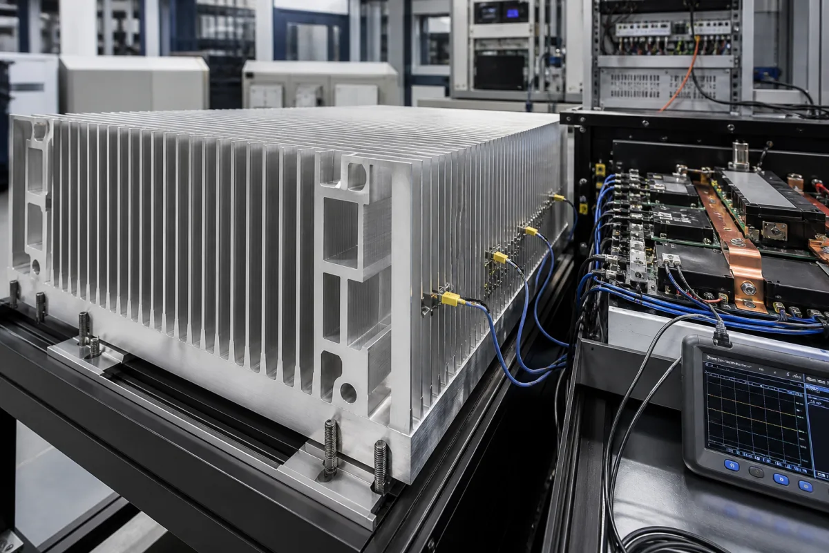
Industrial aluminium heat sink for IGBT power modules: mounting face, grease layer and temperature reference points
Aluminium heat sinks that carry IGBT power modules in drives and converters · 50 µm per 100 mm flatness, Rz 10 µm, a 100 µm grease layer, and where Tc and Ts are measured
In motor drives, inverters and other power converters the IGBT modules are bolted to a large aluminium heat sink, and the heat sink becomes part of the module's thermal and insulation design. The module maker, not the heat sink maker, sets the flatness, roughness, thermal grease and screw torque the mounting face must accept, and the thermal resistance figures in a module datasheet depend on where the case and heat sink temperatures were measured. A heat sink for this duty is therefore specified against a named module's mounting instructions and tested with thermocouples at defined points.
Air-cooled aluminium heat sinks on which IGBT and similar baseplate power modules are mounted in industrial drives, inverters and converters: the module mounting face, thermal interface, screw mounting and the temperature measuring points used to check case-to-heat-sink and heat-sink-to-air resistance. General heat sink selection by thermal resistance and airflow is covered on the Aluminium heat sink page; extruded fin profiles sold by length are covered on the Aluminum extruded heat sink profile page, and water-cooled rectifier heat sinks on the Rectifier heat sink and cooling system page.
CNFX editorial research · Sources checked October 12, 2026 · 3 sources
Flatness within 50 µm per 100 mm, Rz 10 µm and a stencilled grease layer under each module
Fuji Electric's mounting instructions for its EconoPIM and EconoPACK IGBT modules state the limits the heat sink face must meet, and warn that missing them can raise contact thermal resistance or crack the package and cause insulation failure. [1]
Fuji gives the grease amount as thickness (µm) × base plate area (cm²) × grease density (g/cm³) = grease weight (g) × 10⁴, assuming a uniform layer, and recommends checking the spread by removing a module after mounting. It cautions that phase-change materials and thermal sheets can stress the module if they leave a step between fastening points. [1] Editorial calculation: the 100 µm average grease layer is half the 0.2 mm stencil thickness.
Fuji also states that these modules are not designed for dusty environments, because dust clogging the heat sink reduces heat dissipation, and leakage between terminals or creeping discharge can cause short circuits or ground faults. [1]
Item
Fuji Electric requirement for the heat sink and mounting
50 µm or less in absolute value per 100 mm, referenced to the line between the two screw-hole centres; if both convex and concave regions exist, the sum of the maximum and minimum must be 50 µm or less, over the whole mounting area including the screw clamps. [1]
Machining and any later anodising or distortion of a large heat sink must stay inside this band.
Thermal grease
Applied to the module base plate with a stencil; HTC grease at 0.9 W/m·K with an average thickness after spreading of 100 ± 30 µm; stencil masks 0.2 mm thick. [1]
The heat sink face receives a grease film of this order, not a dry contact.
Screws
M5, temporary tightening at 0.5 ± 0.1 N·m, then final tightening in the same order at 2.5–3.5 N·m (V series) or 2.5–6.0 N·m (X series). [1]
Tapped holes and thread depth must take M5 screws at these torques.
Name the exact module type and its mounting instruction when ordering the heat sink, and ask the heat sink maker for a flatness and roughness report taken across each module footprint, the thread size and depth of the module holes, and the surface treatment on the mounting area.
02
Case and heat sink temperature points: holes under the chips and blind holes 2 ± 1 mm below the surface
The case-to-heat-sink resistance Rth(c-s) quoted for a module is only comparable if the heat sink temperature was read at the same point; Semikron Danfoss sets out the IEC 60747 options.
Semikron Danfoss notes that the choice of Ts changes how the total splits between Rth(c-s) and Rth(s-a), while Rth(j-a) at a fixed ambient stays the same, and that the better the heat sink, the larger the difference between the two measuring results. In its SEMiX 3s example with three parallel chips per switch, the temperature differences at the individual chip positions deviated by 10–15%, so it averages the readings under all chips of a switch. [2]
Dynex describes the thermocouples for Tc and heat sink temperature Th as thermally isolated along their length except at the tip, which touches the base plate or the heat sink, with the axis of each thermocouple placed at the centre of a chip. It adds that air-cooled heat sinks spread heat more to neighbouring components than water-cooled ones, and recommends a water-cooled heat sink when measuring module Zth and Rth to represent the worst case. [3] Editorial note: the heat-sink-to-air resistance belongs to the heat sink and its airflow, so ask for it measured on the heat sink itself at the stated air speed.
Temperature
Reference point (Semikron Danfoss, after IEC 60747)
Effect
Case Tc
Measured from underneath through a 1–2.5 mm hole through the heat sink and thermal interface, under each chip. [2]
Gives the case temperature below the chip.
Heat sink Ts1 (method 1)
Heat sink surface from above, at the hottest accessible point nearest the chip. [2]
Cooler point: higher Rth(c-s), lower Rth(s-a); used by Semikron for case-rated modules released before 2014. [2]
Heat sink Ts2 (method 2)
From underneath through a 1–2.5 mm blind hole ending 2 ± 1 mm below the heat sink surface. [2]
Lower Rth(c-s), higher Rth(s-a); used by Semikron for case-rated modules from 2015. [2]
For acceptance tests, agree the module type and losses, the positions and depth of the thermocouple holes, the air speed and inlet temperature, and whether Rth(s-a) will be stated against Ts1 or Ts2.
03
What to send for an IGBT module heat sink
Paste it into your enquiry below or into an email to a maker, then replace every bracket.
Modules: [type and package; number per heat sink; layout; mounting instruction reference]
Losses: [W per module; ambient or inlet air temperature]
Mounting face: [flatness per 100 mm; Rz; surface treatment; tapped holes and depth]
Interface: [grease type and thickness or pad]
Airflow: [fan model or air speed; duct]
Testing: [Tc and Ts measuring points; Rth(s-a) at stated airflow]
Environment: [dust; filtering; cleaning access]
Explore company information and manufacturing capabilities, then discuss the scope of your project with a relevant supplier.
Share this page
Compiled and source-reviewed by the CNFX editorial team.
Each manufacturer above links to the page on that company's own website where the product is listed, with the date we checked it. How we source and review
· Page last updated 13 October 2026
Buyer questions
How flat must a heat sink be for an IGBT module?
Fuji Electric asks for 50 µm or less per 100 mm between the screw-hole centres, over the whole mounting area, with roughness Rz of 10 µm or less. [1]
How thick should the thermal grease be under an IGBT module?
Fuji Electric lists an average of 100 ± 30 µm after spreading for HTC grease applied with a 0.2 mm stencil. [1]
Where is heat sink temperature measured for Rth(c-s)?
Either at the surface beside the module (Ts1) or through a 1–2.5 mm blind hole ending 2 ± 1 mm below the surface under the chip (Ts2), per Semikron Danfoss's reading of IEC 60747-15. [2]
Sources and what still needs a direct check
Sources checked 2026-10-12. Fuji Electric, Semikron Danfoss and Dynex are IGBT module makers; their figures describe how their own modules are to be mounted and measured.