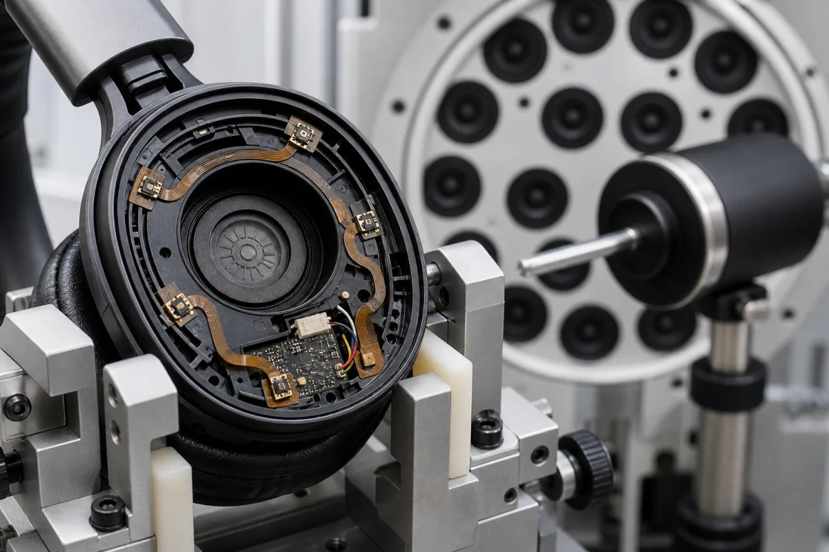
ANC microphone array for noise-cancelling headphones
Microphones for active noise-cancelling headphones and earbuds · Feed-forward, feedback and hybrid placement, MEMS microphone SNR, acoustic overload point, low-frequency roll-off, phase and group delay, part-to-part matching, current and power modes, sealing and the array housing
An ANC microphone array is the set of microphones in each ear cup or earbud of a noise-cancelling headset — an outward-facing reference microphone that hears the ambient noise, an error microphone near the ear that hears what reaches the eardrum, or both — whose signals the ANC processor uses to generate anti-noise through the speaker. Ask three things first: which topology the headset uses and how many microphones go where, what noise level, frequency range and wind exposure the outward microphones face, and what phase, group-delay and part-to-part matching the ANC filter needs at the power budget of a battery device.
Microphones and their mounting for active noise cancellation in headphones, headsets and earbuds: feed-forward, feedback and hybrid microphone sets, the MEMS microphones used, flex circuits, acoustic ports, meshes and the array housing. ANC processor chips and algorithms, speakers, voice-pickup beamforming arrays for calls, conference microphone arrays and hearing aids are outside this page except where compared.
CNFX editorial research · Sources checked October 11, 2026 · 4 sources
Infineon's application note on MEMS microphones in noise-cancelling headsets (AN120538) explains that ANC removes ambient noise in real time by generating anti-noise, "specifically at lower frequencies (<1 kHz), where passive noise isolation is insufficient", and that the number and position of microphones decide the topology. In feed-forward, one microphone per ear cup sits towards the outside and measures the noise before it reaches the ear; it attenuates mid frequencies (1–2 kHz) but cannot check the result, and its outside position exposes it to wind noise. In feedback, one microphone near the ear hears what the user hears and a loop removes noise; it works well at low frequencies but less well at 1–2 kHz because of phase shift in the secondary path. [1]
The hybrid topology uses two microphones — an outward reference microphone for the feed-forward filter and an error microphone at the ear for the feedback filter, the error microphone also adapting both filters. Infineon says it gives the best ANC performance and widest bandwidth at the cost of complexity, cost and size, that ANC above 2 kHz is still not satisfactory, and that over-ear and on-ear designs combine passive isolation with ANC, while in-ear designs, with little room for passive isolation, rely more on microphones with low group delay and flat phase for high-frequency cancellation. [1]
Measured results point the same way. Wu, Qiu, Ma and Guo (ICSV 2016, University of Technology Sydney repository) built one ANC headphone on a floating-point DSP platform and tested feed-forward, feedback and hybrid structures in an anechoic chamber. Feed-forward was more sensitive to the direction the noise came from but performed better than feedback; the hybrid structure partly remedied that directional sensitivity and performed best, giving more than 20 dB noise reduction from 100 to 400 Hz and 5–15 dB from 500 to 800 Hz with optimised parameters. [3]
Editorial note: because the reference microphone's position decides how much the feed-forward path depends on noise direction, ask the supplier for attenuation measured with noise from more than one direction, and compare it with the 100–400 Hz and 500–800 Hz bands reported above. [3]
Editorial note: count the microphones per ear (one for feed-forward or feedback, two or more for hybrid), add any voice-pickup microphones the product also needs, and fix each one's port, mesh and position in the housing before choosing parts.
Bose Corporation's European patent EP 2 856 771 B1 (filed 22 May 2013, granted 13 July 2016) shows how tightly the feedback microphone's position is tied to the earbud acoustics. It describes a feedback microphone acoustically coupled to the ear canal and placed either radially between the point where the driver diaphragm joins the voice coil and the diaphragm edge, or at the junction of the driver module and the passageway to the ear; an optional feed-forward microphone outside the earphone adds a feed-forward signal that is summed with the feedback signal. The claimed geometry uses an acoustic driver of nominal diameter greater than 10 mm (greater than 14 mm in one variant), a nozzle with an open cross-section greater than 10 mm² and a length under 14 mm, and a driver axis meeting the nozzle centreline at more than ±30 degrees (±45 degrees in a dependent claim). The patent states that unpredictable transfer functions between driver, microphone and eardrum can make the feedback loop unstable, heard as squeal radiated into the ear canal. [4]
Editorial note: because the patent ties loop stability to the path between driver, feedback microphone and eardrum, give the microphone-array supplier the driver size, nozzle dimensions and microphone port position together, and ask for transfer-function measurements on the assembled earbud rather than on the bare microphone. [4]
Give the supplier the headset type (over-ear, on-ear, in-ear), ANC topology and number of microphones per ear, positions and port geometry, ANC processor and its interface (analog or PDM digital), expected noise levels and wind exposure, frequency range to cancel, matching requirement, supply voltage and current budget, ingress protection, and quantities.
02
Set SNR, overload, roll-off, phase and power
The application note lists SNR, acoustic overload point (AOP), cut-off frequency, phase response, group delay and current consumption as the key specifications, with tight part-to-part tolerance on cut-off and phase. It asks for a self-noise floor below the ambient noise, an AOP high enough to capture loud noise without clipping (past the AOP distortion exceeds 10%, so it advises choosing a microphone below 1% THD over a wide SPL range), a cut-off frequency of 30 Hz or lower with narrow tolerance, and — for feedback microphones — flat group delay with little variation between microphones. Its IM69D130 digital microphone example has 69 dB SNR and 130 dB SPL AOP, stays below 1% THD to about 128 dB SPL, and measured under 10 µs group delay at 1 kHz. [1]
Infineon's IM73A135 analog differential MEMS microphone lists 73 dB(A) SNR, a 135 dB SPL AOP, −38 dBV sensitivity, part-to-part phase and sensitivity matching of ±1 dB, low-frequency roll-off of 20 Hz, group delay of 2 µs at 1 kHz, selectable 170 or 70 µA power modes, a 1.52–3.00 V supply and IP57 ingress protection at microphone level from a sealed dual-membrane design, and names ANC, transparent hearing, audio zoom and beamforming among the features it enables. [2]
Editorial calculation: a group delay of 2 µs is a phase lag of 360° × 1,000 Hz × 2 µs ≈ 0.7° at 1 kHz, against about 3.6° for 10 µs. Assuming the 73 dB SNR is referenced to 94 dB SPL (1 Pa), the self-noise is about 94 − 73 = 21 dB SPL(A) and the range up to the 135 dB SPL AOP about 114 dB; confirm the reference on the data sheet. [2][1]
03
MEMS microphone makers that name ANC earphones as an application
Memsensing lists silicon MEMS microphones with ANC earphones among the applications; ask for the SNR reference, AOP, roll-off tolerance and group delay of the part it would supply.
04
Reference and error microphones, MEMS element, flex, port and mesh, housing
The two microphone rows call for different figures: the outward reference microphone faces wind and loud noise, so AOP and roll-off come first, while the error microphone sits in the feedback loop, where group delay and phase flatness matter. [1]
Microphone count, sensitivity matching, SNR, AOP, roll-off and group delay for an ANC headset order
The values come from two Infineon parts, the IM69D130 example in the application note and the IM73A135; their SNR figures are stated differently (69 dB and 73 dB(A)), so ask each supplier for the weighting and reference behind its SNR. [1][2]
Field
What it means and published values
Ask the supplier for
Number of microphones
One per ear for feed-forward or feedback; two per ear for hybrid. [1]
1 company lists this product among what they make. Company figures are quoted from each
company's own website; every card states where the relationship came from.
MEMSensing Microsystems (Suzhou, China) Co., Ltd.
Manufacturing site to be confirmed for the order
Its website lists silicon MEMS microphones, with ANC earphones among the applications.
Explore company information and manufacturing capabilities, then discuss the scope of your project with a relevant supplier.
Share this page
Compiled and source-reviewed by the CNFX editorial team.
Each manufacturer above links to the page on that company's own website where the product is listed, with the date we checked it. How we source and review
· Page last updated 13 October 2026
Buyer questions
How many microphones does an ANC headset need?
One per ear for feed-forward or feedback ANC, and two per ear — reference and error — for hybrid ANC. [1]
Why do ANC microphones need low group delay?
Delay and phase variation in the measured noise reduce cancellation, especially at higher frequencies and in feedback loops; one microphone lists 2 µs at 1 kHz. [1][2]
Up to what frequency does ANC work?
Infineon says ANC targets noise below 1 kHz and that even hybrid designs are not satisfactory above 2 kHz, so passive isolation is combined with it. [1]
How much noise reduction does a hybrid ANC headphone achieve?
One measured headphone (Wu et al., ICSV 2016) gave more than 20 dB from 100 to 400 Hz and 5–15 dB from 500 to 800 Hz with the hybrid structure. [3]
Where is the feedback microphone placed in an in-ear ANC earbud?
Bose's patent EP 2 856 771 B1 places it acoustically coupled to the ear canal, either over the driver diaphragm between the voice-coil joint and the diaphragm edge or where the driver module meets the passageway, with a nozzle under 14 mm long. [4]
Sources and what still needs a direct check
Sources checked 2026-10-11. The Infineon application note and product page describe one microphone maker's guidance and parts; the ICSV 2016 paper by Wu, Qiu, Ma and Guo reports anechoic-chamber measurements of the three ANC structures on one headphone. Acoustic performance in your headset must be measured with the microphones and housing offered. Bose Corporation's European patent EP 2 856 771 B1 describes where it places the feedback microphone in an in-ear ANR earphone.