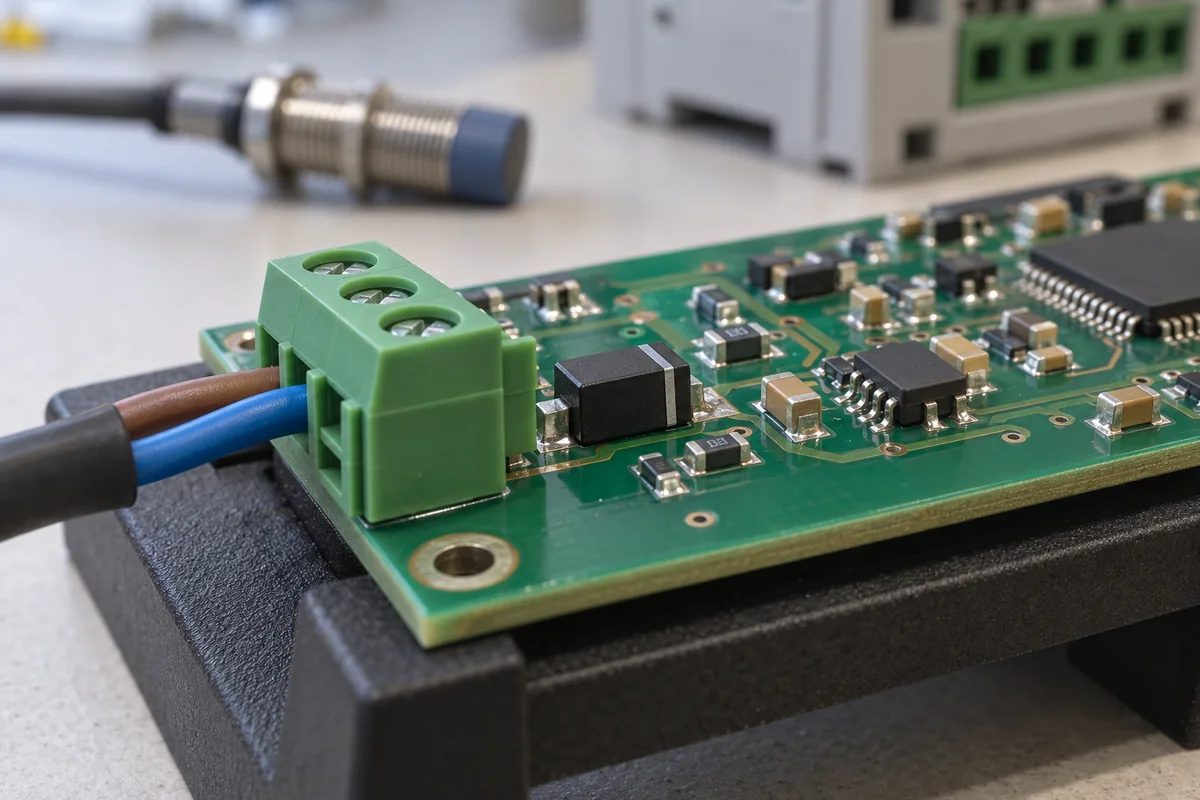
TVS diodes (transient voltage suppressors) · standoff, breakdown and clamping voltage, peak pulse current and power by waveform, capacitance on signal lines, unidirectional or bidirectional, ESD ratings
A transient voltage suppressor (TVS) diode is a clamping device placed between a line and ground: below its standoff voltage it draws only leakage current, and when a surge drives it past breakdown it conducts and holds the line near its clamping voltage, diverting the surge current to ground. Ask three things first: what standoff voltage clears the line's working voltage, what clamping voltage the protected device can survive, and what peak pulse current and power it must take on which test waveform.
Silicon TVS diodes for power, signal, communication and control lines, unidirectional and bidirectional, in surface-mount and leaded packages, including ESD protection arrays. Metal-oxide varistors, gas discharge tubes, fuses and complete surge protective devices are outside this page except where compared.
CNFX editorial research · Sources checked October 12, 2026 · 4 sources
ROHM's application note on selecting TVS diodes describes the part sitting between connector and IC: under normal conditions it does not operate, and when a surge exceeds its breakdown voltage the current flows through it to ground and it clamps the voltage. It tells designers to choose a standoff voltage (VRWM) higher than the line voltage, to check that the leakage (reverse) current, which rises as the signal approaches VRWM, is tolerable, and then to choose the lowest clamping voltage (VCL) available for that VRWM, because a TVS cannot respond fully in the first moments of an ESD event and a higher voltage than VCL may briefly reach the protected device. [1]
Littelfuse's SMBJ datasheet shows the voltage ladder for each part, for example SMBJ24A: 24.0 V standoff, 26.70–29.50 V breakdown and 38.9 V maximum clamping at 15.5 A; and SMBJ5.0A: 5.0 V standoff, 6.40–7.00 V breakdown and 9.2 V clamping at 65.3 A. It gives a breakdown-voltage temperature coefficient of about 0.1% per °C. [2]
Editorial calculation: the SMBJ24A's minimum breakdown of 26.7 V rises to about 26.7 × (1 + 0.001 × 100) ≈ 29.4 V at a junction 100 °C above 25 °C, so clamping rises with temperature too. Its 38.9 V clamp at 15.5 A dissipates about 38.9 × 15.5 ≈ 603 W, the part's 600 W rating; check that the protected IC's absolute maximum voltage is above the clamp at your expected surge current.
Give the supplier the line type (power, signal, data, control), working voltage and polarity, signal frequency or data rate, maximum allowed leakage and capacitance, protected device's absolute maximum voltage, surge and ESD test levels and waveforms (IEC 61000-4-2, -4-4, -4-5 or other), operating temperature, package and footprint, and automotive or other qualification needed.
02
Rate the surge current, power, capacitance and polarity
ROHM states that peak pulse current IPP and peak pulse power PPP on datasheets are rated with either the 10/1000 µs waveform of Telcordia GR-1089-CORE or the 8/20 µs waveform of IEC 61000-4-5, and that the part's ratings must exceed those required by the application; ESD ratings are tested to IEC 61000-4-2 for contact and air discharge. The capacitance between terminals does not affect DC power lines but can distort analog signals, delay and blunt digital signals and degrade eye patterns on communication lines, so capacitance must suit the signal. Unidirectional parts suit lines of one polarity; bidirectional parts are needed for signals that swing both sides of ground. [1]
The SMBJ series is rated 600 W peak pulse power at 10/1000 µs with a 0.01% duty cycle, 30 kV air and contact ESD to IEC 61000-4-2, EFT protection to IEC 61000-4-4, a −65 to 150 °C junction range, and a typical failure mode of short circuit under over-specified voltage or current. [2]
Editorial note: compare parts on the same waveform; a peak pulse power quoted at 8/20 µs is not comparable with one at 10/1000 µs.
03
Specify signal-line ESD diodes by capacitance and clamping
Nexperia's data sheet for its PESD5V0S1BL (2024) describes a very low capacitance bidirectional ESD protection diode in a 1 × 0.6 × 0.48 mm DFN1006-2 (SOD882) package that protects one signal line, rated to IEC 61000-4-2 level 4 for ESD and IEC 61000-4-5 for surge, for handsets, portable electronics, computers and communication systems. [3]
The sheet defines the surge ratings with the 8/20 µs exponential waveform of IEC 61000-4-5 and the ESD rating with ten contact discharges per IEC 61000-4-2 (rise 0.7–1 ns), matching the waveform distinction described in the ROHM note above. Capacitance matters on fast signal lines, while power-line TVS parts such as the 600 W SMBJ series are chosen for surge energy. [3][1][2]
Editorial calculation: 14 V × 12 A = 168 W at the 12 A clamp point, above the 130 W rated peak pulse power, so the ratings are not simply the product of the maximum clamp voltage and current; the clamp rises by about (14 − 10) / (12 − 1) ≈ 0.36 V per amp between 1 A and 12 A.
PESD5V0S1BL (Nexperia)
Condition
Value
Reverse standoff voltage VRWM
25 °C
5 V max
Breakdown voltage VBR
IR = 1 mA
5.5–9.5 V
Leakage IRM
VRWM = 5 V
5 nA typ, 100 nA max
Capacitance Cd
1 MHz, 0 V
35 pF typ, 45 pF max
Clamping voltage VCL
IPP = 1 A / 12 A, 8/20 µs
10 V / 14 V max
Peak pulse power / current
8/20 µs
130 W / 12 A
ESD rating
IEC 61000-4-2 contact; HBM
30 kV; 10 kV
Junction temperature
—
150 °C max
For signal lines, state the data rate (to set the capacitance limit), the line voltage and the ESD and surge levels to meet, and ask for capacitance, clamping voltage at the test current and the package footprint.
04
Compare clamping-to-standoff ratio, including MOSFET-based clamps
Semtech's July 2026 technical article on 48 V USB Power Delivery protection compares its TDS5311P SurgeSwitch, a MOSFET-based clamp, with conventional PN-junction TVS diodes. Its key specifications are a 53 V working voltage, 57 V minimum reverse breakdown voltage, 24 A peak pulse current at 8/20 µs, 63 V clamping voltage at Ipp, 31 mΩ dynamic resistance, ±20 kV contact and ±25 kV air ESD to IEC 61000-4-2, ±4 kV EFT to IEC 61000-4-4, and surge ratings of 24 A (8/20 µs) and 1 kV (1.2/50 µs, 42 Ω) to IEC 61000-4-5. [4]
Semtech states that the MOSFET topology holds a nearly constant clamping voltage across the surge current range and over temperature, giving a clamping voltage up to 30% lower than equivalent PN-junction TVS diodes; it gives about 87 V as the clamping voltage of a conventional TVS solution for 48 V USB PD under similar test conditions, so the TDS5311P's 63 V is about 24 V lower. These are the maker's own comparison figures. [4]
Editorial calculation: the ratio of clamping voltage to standoff (working) voltage is 63 ÷ 53 ≈ 1.19 for the TDS5311P [4] and 38.9 ÷ 24 ≈ 1.62 for Littelfuse's SMBJ24A at 15.5 A; [2] the conventional 87 V figure on a 48 V rail is 87 ÷ 48 ≈ 1.81. A lower ratio leaves more margin to the protected IC's absolute maximum rating, but compare parts only at the same waveform and peak current. [4]
No manufacturer record linked to this product has been confirmed as a TVS diode maker.
The one linked company makes labelling machines; its "clamping device" is a mechanical part, not a TVS diode, so it is not shown. Send your specification to have it matched against manufacturer records.
06
Trace the device characteristics
This is a functional reference built from the sources cited; it is not one maker's specification.
Fill the specification fields with values for your circuit
A TVS diode quotation needs values for your circuit. The table explains each field, gives published values where a reviewed source states them, and says what to obtain from the supplier.
The manufacturer below lists TVS diodes on its own website; each card links to the page reviewed. Confirm ratings, materials and approvals for your order.
WAYON Electronics Co.,Ltd
Manufacturing site to be confirmed for the order
Lists TVS diodes among its circuit-protection products, alongside ESD protection, PPTC fuses and gas discharge tubes.
Explore company information and manufacturing capabilities, then discuss the scope of your project with a relevant supplier.
Share this page
Compiled and source-reviewed by the CNFX editorial team.
Published product pages show what a company offers, not tested performance. Confirm the legal seller, factory and scope for your order. How we source and review
· Page last updated 13 October 2026
Buyer questions
How do I choose TVS standoff voltage?
ROHM says to choose a standoff voltage higher than the voltage on the line, then the lowest clamping voltage available for it. [1]
Why does the waveform matter?
Peak pulse ratings are given at 10/1000 µs (Telcordia GR-1089-CORE) or 8/20 µs (IEC 61000-4-5); Littelfuse rates SMBJ at 600 W on 10/1000 µs. [1][2]
Unidirectional or bidirectional?
ROHM uses unidirectional parts on single-polarity lines and bidirectional parts where signals swing both sides of ground. [1]
What ESD level can a small signal-line protection diode withstand?
Nexperia's PESD5V0S1BL data sheet gives 30 kV contact discharge to IEC 61000-4-2 and 12 A at 8/20 µs, with 35 pF typical capacitance. [3]
Do MOSFET-based surge clamps clamp lower than TVS diodes?
Semtech states its TDS5311P clamps at 63 V at 24 A (8/20 µs) on a 53 V working voltage, against about 87 V for a conventional TVS solution on 48 V USB PD; compare at the same waveform and current. [4]
Sources and what still needs a direct check
Sources checked 2026-10-12. ROHM, Littelfuse, Nexperia and Semtech are semiconductor makers describing selection of their own protection devices; their figures are examples, not limits for other parts.