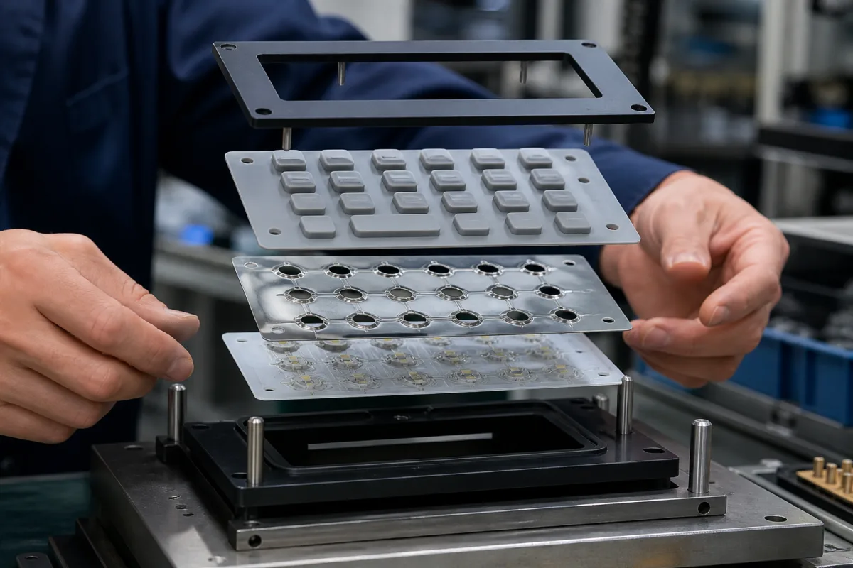
Keypad assembly: a silicone rubber keymat over a metal-dome array on a printed circuit board, held by a bezel
Equipment keypads · bezel, silicone rubber keymat, metal dome array and PCB stacked on alignment pins; 0.4–0.7 mm dome travel against 0.8–1.5 mm rubber travel; snap ratio 40–60%; gold-plated pads
A keypad of this kind is not a single part but a stack: a bezel or fascia on top, a moulded silicone rubber keymat whose keys poke through it, a sheet of stainless snap domes under the keys, and a circuit board with a switch pad under each dome. The rubber gives the key its shape, legend and seal; the dome gives the click and makes the contact. Three choices decide how the assembly feels and lasts: whether the contact is made by the rubber key's own conductive pill or by a metal dome under it, the force, travel and life of that switch, and how the layers are aligned, vented and plated so the contact stays reliable.
Multi-layer key assemblies for equipment: bezel or fascia, silicone rubber keymat, metal or polyester snap-dome array and the PCB switch pads beneath, with their force, travel, snap ratio, life, contact plating, alignment and tolerances. Complete SIP desk phones are covered on the Enterprise VoIP desk phone page and their handset earpieces on the Handset receiver transducer page; computer keyboards on the Ergonomic keyboard page; machine operator stations with touch panels, E-stops and pushbuttons on the HMI interface operator station page and their housings on the Operator-station mounting enclosure page; rotary selector switches on the Rotary function selector switch page.
CNFX editorial research · Sources checked October 13, 2026 · 3 sources
Bezel, silicone keymat, dome array and PCB: what each layer does and how they are lined up
Diamond HMI's rubber keypad design guide describes two ways of adding a metal dome to a silicone keypad: the domes can be attached to the underside of the keypad, in which case the rubber web acts only as a hinge, or supplied on a separate dome array that the user sticks to the PCB. Either way, it recommends hard gold contact pads on the board where possible for the greatest resistance to wear, and advises life testing the specific dome and plating combination before production. [1]
For keys that switch with a carbon pill instead, the same guide recommends 30–50 µin of gold over 100–200 µin of nickel on the PCB pads to give a contact resistance below 100 Ω, or at least 200 µin of nickel if no gold is used; shorting pads with 0.5 mm tracks and 0.6 mm gaps, the largest practical number of shorting paths, and a pad at least 1.25 times the pill size. Its dome pad drawings show a vent hole through the board. [1]
Alignment is designed into the keymat: Diamond HMI suggests alignment holes in the keypad base for the fascia and the PCB, or pull-through features that tie the keypad into holes in the board, so that each key sits central to its fascia aperture and its contact pad. Minimum key height is keypad base thickness plus bezel thickness plus key stroke plus 0.5 mm. [1] Editorial calculation: with an assumed 1.0 mm base, 1.5 mm bezel and 0.8 mm stroke, the key must stand at least 3.8 mm tall.
Moulded silicone shrinks and varies, so tolerances widen with size. Diamond HMI gives ±0.1 mm below 10 mm, ±0.15 mm at 10–19.9 mm, ±0.2 mm (±0.15 mm precise) at 20–29.9 mm, ±0.3 mm (±0.25 mm precise) at 30–49.9 mm and 0.6% (0.4% precise) above 50 mm, and suggests splitting a large key area into separate keypads to hold tighter tolerances. Epec's table runs from ±0.13 mm up to 25 mm to ±0.62 mm at 100.1–150 mm and 0.5% above that, and lists linear shrinkage of 3–4.5% for silicone and 3–5% for the carbon conductor. [1][2]
Send the bezel drawing with apertures, the keymat outline and key heights, the PCB pad layout and plating, whether the domes are to be fixed to the keymat or supplied as an adhesive array, and how the keymat is located on the board.
02
Conductive rubber key or metal dome underneath: force, travel, snap ratio and life
A rubber key switches by collapsing its moulded web until a conductive pill on its underside bridges the PCB pad; a metal dome switches by snapping through and touching the centre pad itself. The published figures show what each gives.
Diamond HMI defines snap ratio as (F1 − F2) / F1, where F1 is the actuation force and F2 the contact force, and advises 40–60%, going lower only to trade tactile feel for longer life; higher-durometer silicone, more actuation force or more stroke all shorten switch life. Against rocking it suggests a return force of 30–35 g, stabilising posts or multiple contacts per key, short webs at close to 40°, and 80–150 g for keys 10–15 mm high or 150–175 g for keys 15–25 mm high. [1] Epec's force tolerances widen with force, from ±15–20 g at 50 g to ±50 g at 200 g, and it rates tactile feel as fair at 200 g. [2] Editorial calculation: a key with F1 = 150 g and F2 = 75 g has a snap ratio of 50%.
Snaptron reports that its SQ-Series four-leg domes, roughly square, reach 10 million cycles, twice its standard domes, in nine standard sizes from 4 to 12 mm, and that the wide shape allows high trip forces for the size. [3] Diamond HMI also offers embossed polyester domes with a printed silver pad underneath where low travel and low cost are wanted. [1]
The two sources state rubber-key life differently: Epec gives 1,000,000 cycles for its keypads, while Diamond HMI gives more than 30 million operations for carbon pills. Ask the supplier which figure applies to the key, web and pill design being quoted, and at what force. [2][1]
Property
Silicone key with conductive pill
Metal snap dome under the key
Travel
0.8–1.5 mm [2]; stroke near 0.8 mm advised against rocking [1]
60–300 g [2]; 125–150 g with a 40–60% snap ratio recommended [1]
150–2,250 g across 6–20 mm domes [1]; 200 g on a 4 mm Snaptron SQ04200N [3]
Life
1,000,000 cycles [2]; carbon pills above 30 million operations [1]
10 million cycles for Snaptron SQ-Series four-leg domes [3]
Contact
Carbon pill below 150 Ω at 100 g; printed carbon below 800 Ω at 300 g [1]; below 200 Ω [2]
Stainless steel, nickel plated to improve contact resistance [3]
State the key force, travel and snap ratio wanted, or the dome size and trip force, the life in cycles and the test force behind it, the contact resistance limit, and the operating temperature range.
03
Keypad stack data for a quotation
Paste it into your enquiry below or into an email to a maker, then replace every bracket.
Explore company information and manufacturing capabilities, then discuss the scope of your project with a relevant supplier.
Share this page
Compiled and source-reviewed by the CNFX editorial team.
Each manufacturer above links to the page on that company's own website where the product is listed, with the date we checked it. How we source and review
· Page last updated 13 October 2026
Buyer questions
Why put a metal dome under a rubber keypad?
The dome provides the tactile snap and makes the contact; Diamond HMI notes that with domes on the keypad underside the rubber web acts only as a hinge. [1]
How far does a metal dome key travel?
Diamond HMI gives 0.4–0.7 mm (typ.) for metal domes, against 0.8–1.5 mm listed by Epec for rubber keys. [1][2]