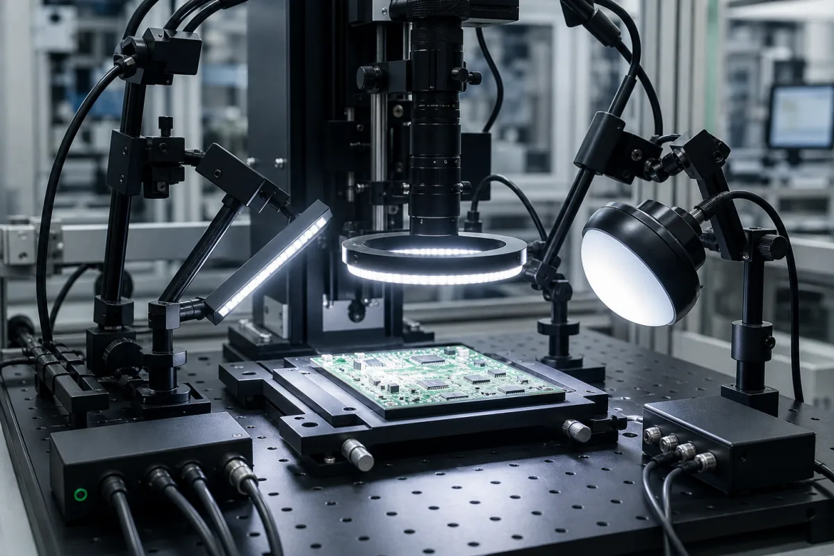
LED lighting system for machine vision (ring, bar and dome lights with strobe control)
LED lighting for machine vision · ring, bar and dome lights by technique, strobe overdrive and duty cycle, trigger wiring and supply current
A machine vision LED lighting system is the set of lights, such as ring, bar, dome, coaxial and back lights, and their drivers or strobe controllers that illuminate a part for a camera so that the features to be inspected show with consistent contrast. Ask three things first: which illumination technique the feature needs, whether the light runs continuously or strobed and within what pulse and duty-cycle limits, and how it is triggered and powered from the vision system.
LED lights and strobe controllers for machine vision and automated inspection: ring, bar, dome, coaxial, back and dark field lights. LED modules and light engines for general and industrial luminaires are covered on the LED light module page; area lighting fixtures, vehicle lamps and cameras are outside this page.
CNFX editorial research · Sources checked October 12, 2026 · 4 sources
Machine Vision Direct's guide to illumination techniques divides them into back lighting, diffuse (full bright field), partial bright field (directional) and dark field. Back lighting gives dark silhouettes against a bright background for presence of holes and gaps, part placement and measurement; diffuse lighting, in hemispherical dome, cylinder or on-axis form, is used on shiny specular or mixed-reflectivity parts, with dome lights effective on curved specular surfaces and needing close proximity to the part. [4]
The guide describes partial bright field as directional, good for contrast and topographic detail but producing a hotspot when used on-axis with specular surfaces, and dark field as low or medium angle light that needs close proximity, particularly for circular heads, so that light from a mirror-like surface is reflected away from the camera and only edges and small features such as scratches return to it. It notes that a standard bright field bar light may also be used in dark field mode, whereas a diffuse light is used only as diffuse. [4]
Editorial note: try the candidate techniques on real parts with the actual camera and lens, since the guide ties the result to the geometry of camera, part and light rather than to the light alone.
Give the supplier the parts and features to inspect, surface finish and colour, field of view, working distance and mounting space, camera and exposure time, line speed and trigger, continuous or strobed operation, wavelength, supply voltage and connectors, IP rating and quantity.
02
Set strobe overdrive, pulse length and duty cycle
Smart Vision Lights describes three driver types: continuous lights designed to stay on indefinitely without a duty cycle; Multi-Drive lights with both continuous and OverDrive strobe drivers built in; and OverDrive lights that can be strobed at up to 10 times the intensity of its continuous drivers, with a limited pulse length and a 10% duty cycle unless a light's data sheet states otherwise. [1] Its technology page adds that its NanoDrive lights at a 1 µs pulse and 10% duty cycle can produce 100,000 strobes per second, and that its integrated OverDrive controller takes NPN and PNP trigger signals. [2]
Its ODRL300 OverDrive ring light data sheet gives 24 V dc input, up to 14 A per connector and 28 A in total during the strobe (336 W per connector, 672 W in total), a maximum total average current of 2.8 A, a maximum duty cycle of 10%, up to 5,000 strobes per second, a maximum single pulse of 125 ms, 0-10 V analog intensity control from 10 to 100%, an M12 5-pin connector, IP50 and a stated lifespan of 100,000 h. It defines duty cycle as strobe time divided by rest time, giving 100 ms rest for a 10 ms strobe. The same sheet lists a maximum total average wattage of 672 W, which does not match its 2.8 A average current at 24 V; confirm the average power with the maker. [3]
Editorial calculation: at 24 V, 2.8 A average is 24 × 2.8 = 67.2 W, a tenth of the 672 W strobe peak. With duty cycle defined as strobe over rest, a 10 ms strobe needs 10 + 100 = 110 ms per cycle, or about 9 strobes per second at that pulse length; size the 24 V supply for the 28 A peak and the line rate for the rest time. [3]
03
Ring, dome and back lights, strobe controller and trigger inputs
The light head sets the illumination technique; the driver decides whether it runs continuously or in OverDrive strobe pulses at a limited duty cycle.
Explore company information and manufacturing capabilities, then discuss the scope of your project with a relevant supplier.
Share this page
Compiled and source-reviewed by the CNFX editorial team.
Each manufacturer above links to the page on that company's own website where the product is listed, with the date we checked it. How we source and review
· Page last updated 13 October 2026
Buyer questions
When is a dome light used in machine vision?
Machine Vision Direct describes dome diffuse lights as effective on curved, specular surfaces, needing close proximity to the part. [4]
What does overdrive strobing allow?
Smart Vision Lights states its OverDrive lights strobe at up to 10 times continuous intensity, with a 10% duty cycle unless the data sheet states otherwise. [1]
How is strobe duty cycle defined?
Smart Vision Lights' ODRL300 data sheet defines it as strobe time divided by rest time, so a 10 ms strobe needs 100 ms rest at 10%. [3]
What does dark field lighting show?
Low-angle light reflects away from the camera on a mirror-like surface, so only edges and small features such as scratches appear bright. [4]
Sources and what still needs a direct check
Sources checked 2026-10-12. Smart Vision Lights describes its own drivers and an ODRL300 data sheet (reviewed from a distributor-hosted copy); Machine Vision Direct is a vision lighting distributor describing illumination techniques.