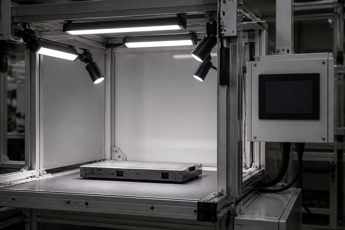
Programmable lighting system for multi-shot inspection: lights or zones fired in a stored sequence, one per camera exposure, for photometric stereo and multi-light imaging
Machine vision · sequenced multi-light inspection: one light direction or zone per exposure, photometric stereo with at least three directions, recipe sequences stored in the controller, µs pulse and delay settings
Some surface defects only show up when the same part is photographed three, four or more times under light from different directions, or in different colours, and the images are combined. A programmable lighting system does the switching: a controller holds a recipe that lights one direction, zone or colour at a time, each in step with a camera trigger, and then resets for the next part. The questions are how many directions and at what angles the software needs, how many steps a stored sequence can hold, and how finely and repeatably the controller can time each pulse against the exposure.
Multi-light and multi-zone lighting set-ups for machine vision whose controller sequences different lights, zones, intensities or colours across successive camera exposures of the same part: photometric stereo lighting, multi-shot and multispectral lighting sequences, light sequencers, and multichannel LED controllers used in sequence mode with their trigger and timing inputs. Machine vision lights and controllers as a category, including ring, dome, coaxial and back lights, are covered on the Machine vision illumination unit page, and single-shot strobe overdrive, pulse length and duty cycle on the LED lighting system for machine vision page; tiered RGB ring lights for solder-joint AOI on the LED illumination system for solder-joint inspection page; vision boxes that drive lights from built-in strobe outputs on the Image processing unit with built-in LED strobe control page; angled bar-light arrays on the LED illumination array for machine vision page; LED ring lights with sector control on the Lighting Module page; light-tight inspection cabinets on the Controlled lighting chamber page; fringe and laser projection for solder paste height on the solder paste inspection Illumination system page; building and smart-home dimmers on the Lighting controller page.
CNFX editorial research · Sources checked October 13, 2026 · 4 sources
Photometric stereo: at least three known light directions, four to six for shadows, slant between 30° and 60°
MVTec's HALCON reference for its photometric_stereo operator sets the lighting requirements a sequenced set-up must meet. It needs at least three images of the same object, each taken with a different and known direction of illumination, while the camera stays fixed and looks perpendicular to the scene. Because shadows reduce the number of directions available at some points, MVTec advises more than three light sources, calls four to six light sources reasonable, and gives a rule of thumb of slant angles between 30° and 60° with tilt angles spread evenly around the object. [1]
The same reference states the assumptions behind the algorithm, which is based on Woodham's method: a telecentric lens or long focal distance, light sources that each deliver a parallel, uniform beam (telecentric illumination or distant point sources), and a diffusely reflecting surface; mirroring or glossy regions cannot be reconstructed. It separates the 3D shape of the surface, as local gradients and a relative height field, from its 2D texture, the albedo, so that small surface inconsistencies or embossed print can be inspected independently of the print. MVTec also cautions that the method is no alternative to 3D reconstruction for absolute heights. [1]
MVTec specifies each direction by two angles: slant, measured from the camera's optical axis, and tilt, measured in the object plane, where 0° means light from the right, 90° from the top and 180° from the left of the image. [1] Editorial note: with four lights, an even tilt spread puts them 90° apart; record the measured slant and tilt of each light as installed, because the software takes them as inputs.
Tell the lighting supplier which software will process the images, the number of directions it expects, the slant and tilt of each light, the field of view and working distance, and whether the surface is matt or glossy.
02
What the controller stores and times: sequences per program, per-channel intensity, pulse width and trigger delay
Smart Vision Lights' LED Light Manager (LLM), sold by Machine Vision Direct, shows the sequencer as a separate box: it can run multiple lights, or up to four zones of one integrated photometric or multispectral ring light, and each program can contain up to six sequences with up to four lights set to on, off, any intensity in between or OverDrive strobe. It is programmed from a browser over Ethernet, and the distributor states that it is not a light driver but a sequencing tool. [3]
Gardasoft's own controllers can also be set to sequence. Novus Light reported a firmware update that lets multichannel Gardasoft controllers output, on each trigger, a series of pulses at different intensities on different channels; the length of the sequence and each channel's intensity and pulse width are configurable, the sequence repeats from the start when it finishes, and a second input or an Ethernet command resets it so that lights and cameras start in step. For conveyor lines the article points to Gardasoft's CC320 trigger timing controller to generate camera and light triggers from a part sensor and encoder and to drive a reject gate. [4]
Editorial calculation: on the RTCC4's standard models, pulse width is set in 20 µs steps, so a 100 µs exposure-matched pulse is five steps; the fast-pulse models reach 1 µs steps. When delay plus pulse is no more than 1 ms, the datasheet's 3 µs delay repeatability is 0.3% of that 1 ms window. [2]
Smart Vision Lights also lists multispectral imaging for the LLM, where the colour of each LED zone, not a filter in front of the sensor, selects the spectral band of each image in the sequence. [3]
Item
Smart Vision Lights LLM
Gardasoft RTCC4 (RT-series drive with trigger timing)
Lights or channels
Multiple lights, or up to four zones of one light [3]
Up to 2 A continuous or pulsed (-2), or 3 A continuous and 20 A pulsed (-20); max 30 W per channel [2]
State the number of lights or zones and images per part, the intensity and pulse width of each step, the camera exposure and trigger source, the part rate, how the sequence is reset between parts, and whether the controller must also drive the lights or only sequence separate drivers.
03
For a quotation on a sequenced lighting set-up
Paste it into your enquiry below or into an email to a maker, then replace every bracket.
Method: [photometric stereo; multi-shot; multispectral; software used]
Lights: [number of directions or zones; slant and tilt of each; colours]
Sequence: [images per part; intensity and pulse width per step]
Timing: [camera exposure; trigger source; delay; part rate]
Reset: [hardware input; Ethernet command]
Drive: [current per channel; continuous or pulsed; overdrive]
Interface: [Ethernet; RS232; digital outputs for cameras or reject gate]
Mounting: [field of view; working distance; enclosure]
Explore company information and manufacturing capabilities, then discuss the scope of your project with a relevant supplier.
Share this page
Compiled and source-reviewed by the CNFX editorial team.
Each manufacturer above links to the page on that company's own website where the product is listed, with the date we checked it. How we source and review
· Page last updated 13 October 2026
Buyer questions
How many lights does photometric stereo need?
MVTec's HALCON reference requires at least three known illumination directions and advises four to six light sources to cope with shadows, at slant angles between 30° and 60°. [1]
How many sequences can a lighting sequencer store?
Smart Vision Lights' LLM holds up to six sequences per program, each with up to four lights at set intensities or in overdrive strobe. [3]
How short can a sequenced LED pulse be?
Gardasoft's RTCC4 datasheet gives 20 µs to 999 ms on standard models and 1 µs to 999 ms on fast-pulse models. [2]
Can a multichannel LED controller change intensity from one image to the next?
Novus Light reports that multichannel Gardasoft controllers can output a configurable series of pulses at different intensities on different channels on each trigger. [4]
Sources and what still needs a direct check
Sources checked 2026-10-13. MVTec's operator reference sets the lighting geometry photometric stereo needs; a Gardasoft datasheet published by its distributor Pyramid Imaging gives controller timing; Machine Vision Direct's page for the Smart Vision Lights LLM and a Novus Light news item describe stored and per-trigger sequences.