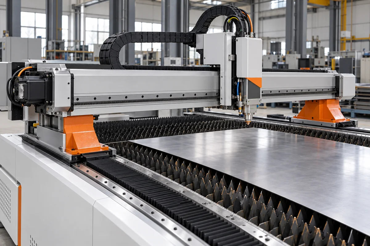
Laser cutter gantry and head motion system: the moving crossbeam, its drives and the carriage that carries the cutting head
Flat-bed laser cutting machines · steel, extruded aluminium and carbon-fibre crossbeams · dual rack-and-pinion or linear-motor drives · 1.0 to 6 g published acceleration
On a flat-bed laser cutter the sheet stays still and the optics move: a crossbeam rides on two side rails, a carriage runs along the beam and a short vertical axis lifts the cutting head. This page looks at two choices in that assembly: what the beam is made of, since its mass is accelerated on every move, and whether it is driven by geared racks or by linear motors.
The moving motion assembly of flat-bed CNC laser cutting machines: the crossbeam (gantry), its two-sided longitudinal drives, the carriage running along the beam and the Z axis that holds the cutting head, with their guides and position feedback. The complete machine, with laser source, enclosure and assist gas, is covered on the CNC fibre laser cutting machine page and the head optics on the Cutting head page. Portal structures and rail tracks of plasma and oxy-fuel cutters are covered on the Cutting gantry page, electrically preloaded dual-pinion drives for long beds on the X-axis rails and drive page, and general Cartesian modules on the XY gantry system page.
CNFX editorial research · Sources checked October 17, 2026 · 5 sources
Beam material decides moving mass: a 62 kg carbon-fibre beam against its welded steel original
Researchers at the University of Minho redesigned the runway beam of a laser cutting machine built by Adira, which carries the cutting head car and the main beam mirrors and lens. Their paper states that at the 3 and 4 g already enabled by linear motors, the mass and limited stiffness of steel or aluminium runway frames prevent the required cutting precision. [1]
The original beam was two welded steel box girders stiffened inside by X-, C- and V-shaped plates. The replacement is a vacuum-infused sandwich of carbon-fibre epoxy skins on a polyester foam core, about 7 mm thick in total with a 3 mm foam core, bonded from four kinds of moulded parts. The largest composite beam weighs 62 kg, 64 % less than the steel beam it replaces. [1]
In the authors' finite-element model, the first flexible mode of the composite beam is at 153.15 Hz against 18.26 Hz for the steel beam, and the 0 to 500 Hz range holds 7 modes for the composite beam against 47 for steel. The paper also warns that the fully equipped composite beam still showed worrying behaviour at frequencies in the possible working range, and estimates it at about 6.6 times the cost of the steel beam. [1]
Editorial calculation: if 62 kg is 64 % lighter, the steel beam weighed about 62 / 0.36 = 172 kg. Accelerating the beam alone at 3 g (29.4 m/s²) then takes about 1.8 kN for the composite beam and 5.1 kN for the steel one, before the carriage, Z axis and head are added. Both figures assume the 64 % refers to the same, largest beam size. [1]
Machine builders publish their beam choices in different terms. G.WEIKE describes an aviation-aluminium gantry extruded on a 4,300-ton press and aged to 6061-T6 strength [4]; DurmaPress lists an aviation-aluminium beam and Z axis on a welded, heat-aged bed [5]; Eagle uses a carbon-fibre composite traverse and states that it stays rigid at 6G acceleration [2].
02
Two pinions on two racks, or linear motors with absolute scales
Both drive layouts move the beam from both ends at once. What changes is how motor torque becomes beam travel and what reports the position back.
G.WEIKE builds its LF3015L axes from Yaskawa servo motors, Motoreducer gear reducers and APEX racks and quotes a positioning accuracy of 0.02 mm and a cutting acceleration of 1.0G. [4] DurmaPress lists a gantry double-drive structure with racks and gears on both sides for its DS series. [5]
Eagle puts linear motors on all axes: the mover runs over the stator without contact, so there is no screw, belt or gear play, and position comes from Renishaw RESOLUTE absolute optical encoders with up to 1 nm measurement resolution and a 22 kHz update rate. Because the scales are absolute, Eagle states the machine is ready to cut about 15 seconds after power-on without a homing run. [3]
The Adira machine studied at Minho also runs on four linear motors, two at the ends of the runway beam and two in the car that carries the cutting head along it. [1]
Ask whether the quoted acceleration is a peak axis value or the value used while cutting, and whether accuracy figures come from the rack drive with motor encoders or from linear scales on the axis.
03
Published travel, speed, acceleration and accuracy for three gantry layouts
Editorial calculation: DurmaPress gives positioning accuracy per metre. Assuming the error adds up linearly along the axis, its 4,010 mm Y travel could accumulate up to about ±0.12 mm end to end, while the ±0.02 mm repeat figure describes returning to the same point. Ask for the measured error over the full travel rather than the per-metre value. [5]
Machine and drive
Beam
Published figures
G.WEIKE LF3015L, servo, reducer and rack
Extruded aviation aluminium
3,000 × 1,500 mm working area; 80 m/min max. speed; 1.0G max. acceleration; ±0.02 mm repeat positioning [4]
DurmaPress DS series, double rack-and-gear drive
Aviation aluminium beam and Z axis
Y 4,010 mm, X 2,010 mm, Z 80 mm travel; X/Y ≥100 m/min; X/Y 1.5g; positioning ±0.03 mm per metre; repeat ±0.02 mm [5]
Eagle, linear motors on all axes
Carbon-fibre traverse
Up to 6G stated; absolute encoders to 1 nm resolution [2][3]
04
Gantry motion data to request with a laser cutter quote
Paste it into your enquiry below or into an email to a maker, then replace every bracket.
Beam: [material; mass of beam, carriage and Z axis]
Drive: [rack-and-pinion or linear motor; motors and reducers per side]
Feedback: [motor encoder or linear scale; absolute or incremental]
Axes: [X, Y, Z travel]
Dynamics: [max. speed; acceleration while cutting and peak]
Accuracy: [positioning over full travel; repeatability; test method]
Explore company information and manufacturing capabilities, then discuss the scope of your project with a relevant supplier.
Share this page
Compiled and source-reviewed by the CNFX editorial team.
Each manufacturer above links to the page on that company's own website where the product is listed, with the date we checked it. How we source and review
· Page last updated 17 October 2026
Buyer questions
Why does beam material matter on a laser cutter?
The beam is accelerated with every move. In the Minho study a carbon-fibre beam weighed 62 kg, 64 % less than the steel original, and its first flexible mode rose from 18.26 Hz to 153.15 Hz. [1]
What acceleration do laser cutter gantries reach?
Published figures range from 1.0G (G.WEIKE LF3015L, rack drive) and 1.5g (DurmaPress DS) to 6G stated by Eagle for its carbon-fibre traverse on linear motors. [4][5][2]
Do linear-motor gantries need homing?
Eagle states that with absolute linear encoders its machines are ready about 15 seconds after power-on without a homing routine. [3]
Sources and what still needs a direct check
Sources checked 2026-10-17. One conference paper from the University of Minho on a production laser cutter beam, two Eagle technology pages, and product pages from G.WEIKE and DurmaPress.