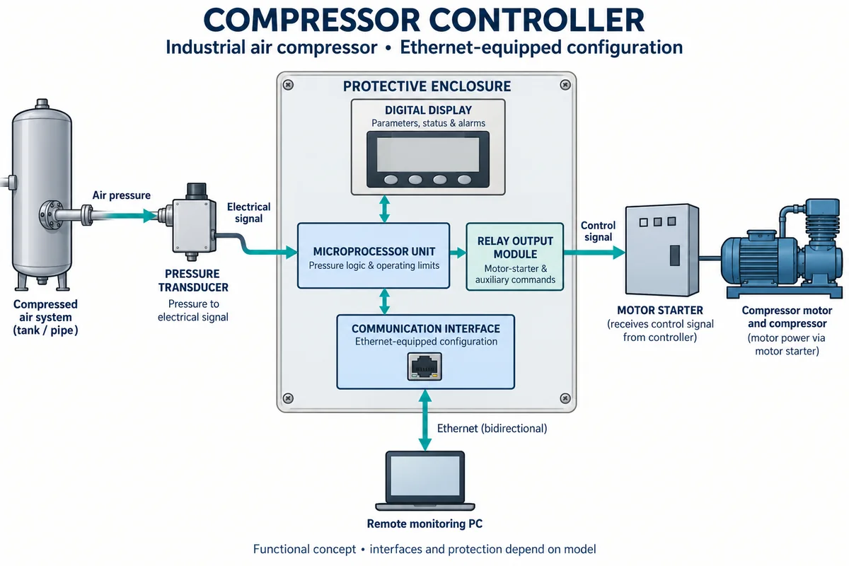
Compressor controller (air compressor and system control)
On-board compressor control and coordinated compressed-air supply
A compressor controller manages the machine’s operating state; a network or master controller coordinates the compressor room. Define the supported machines, pressure measurement and control responsibility before comparing energy or pressure-band claims.
Electronic controllers for industrial air compressors and compressor rooms: on-board compressor controllers, network and sequencing controllers, system master controls and pressure/flow controllers. Compressors themselves, variable-frequency drives sold alone, dryers and building management systems are outside this page except where compared.
CNFX editorial research · Sources checked October 18, 2026 · 4 sources
Identify the control mode and the compressor it operates
The Compressed Air Challenge’s May 2026 fact sheet distinguishes start/stop, load/unload, modulation, multi-step and variable-speed strategies. It qualifies its unloaded rotary-screw example with “in most cases” and reports consumption of 15–35% of full-load horsepower while doing no useful work. That range is not a specification for every compressor or control mode. [1]
DOE’s control-strategy tip sheet describes how individual and multiple-machine controls respond to changing demand. Obtain the actual machine’s power/flow curve and permitted operating states; the controller label alone does not establish part-load performance. [2]
Editorial calculation: assuming a hypothetical fixed-speed machine spends half of the same elapsed operating period fully loaded at 100% reference power and half unloaded at 25%, with zero useful unloaded delivery, unchanged full-load air delivery and no transition losses, average power is 0.5 × 100% + 0.5 × 25% = 62.5% of reference full-load power. The assumed unloaded value lies inside the cited example range. This is neither manufacturer-published performance nor measured operation or a saving versus another control strategy. [1]
02
Coordinate machine states with demand and storage
DOE distinguishes networked on-board controls from a system master that coordinates the installation. Its pressure/flow controller separates supply and demand using storage and does not directly control a compressor. Keep this flow-control device separate from the electronic compressor controller being purchased. [2]
CAC discusses operating needed machines efficiently while using a trimming function to match changing demand. Its pressure guidance also warns that sudden demand can pull pressure below the required minimum unless controls and storage are matched. Obtain the demand/pressure profile and the supported start, load, unload and trim logic for the actual machines. [1]
CAC gives an approximate energy relationship of about 1% per 2 psi pressure difference; Atlas Copco gives about 7% per bar in its controller discussion. These are source estimates, not measured savings for the offered controller or permission to reduce pressure without checking demand, losses and storage. The earlier derived 10 psi saving estimate is not used as a site result. [1][4]
The ETL entry for SAM4.0-16 records affirmative answers for holding pressure within ±0.2 bar of setpoint from a single pressure transducer as demand varies over 10–100% of the combined continuous rated compressor output. It separately records a transducer measurement criterion of ≤ ±0.5% of full scale across its rated pressure range and −25 to 80 °C. These are the listing’s stated conditions; the temperature is not a published ambient range for the whole controller cabinet. [3]
03
Match controller capacity and interfaces to the installed fleet
Atlas Copco lists different central-controller capacities and logic. Its description distinguishes sequencing from selection based on machine type, size, flow, power and status. Count supported machines and verify the intended interfaces instead of comparing only the model tier. [4]
3 companies list this product among what they make. Company figures are quoted from each
company's own website; every card states where the relationship came from.
HollySys
TBC
Its official CCS page lists dedicated compressor control systems. Confirm the exact air-compressor duty and control package; a general DCS listing alone is not the basis.
Explore company information and manufacturing capabilities, then discuss the scope of your project with a relevant supplier.
Share this page
Compiled and source-reviewed by the CNFX editorial team.
Each manufacturer above links to the page on that company's own website where the product is listed, with the date we checked it. How we source and review
· Page last updated 13 October 2026
Buyer questions
Does unloaded screw-compressor power equal a fixed percentage for all machines?
CAC qualifies its 15–35% example range. Obtain the actual compressor’s power/flow behavior and control conditions rather than assigning the range to every machine. [1]
Does a pressure-reduction rule give measured controller savings?
No. CAC and Atlas Copco provide approximate relationships. Actual pressure, demand, storage and power measurements are needed for the installation. [1][4]
Is the ETL transducer temperature range a control-cabinet ambient specification?
The entry attaches that range to the pressure-transducer measurement criterion. Obtain the whole controller’s permitted ambient conditions separately. [3]
Sources and evidence scope
Sources checked 2026-10-18. CAC guidance, DOE’s dated system-control tip sheet, the identified ETL product entry and Atlas Copco’s controller descriptions. Model capacities and listing conditions are not independent measurements of the proposed installation.