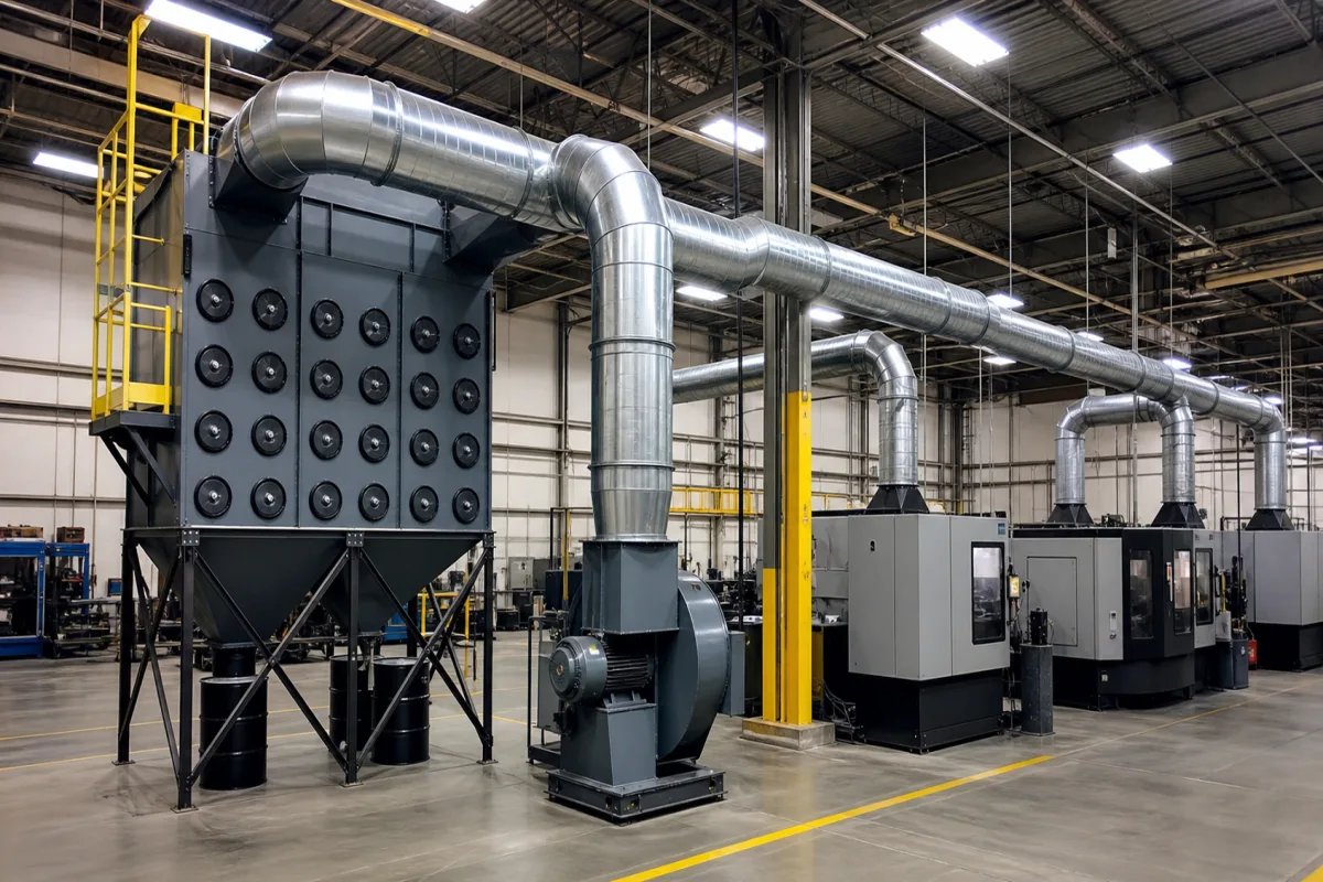
Dust extraction hoods and duct network for metal grinding, polishing and machine-tool enclosures (local exhaust ventilation)
Metalworking local exhaust · hoods on grinding, polishing and buffing machines and machine-tool enclosures, branch and main duct velocities, entry losses
This is the part of a metalworking dust extraction system between the dust source and the collector: the hood on each grinding wheel, buffing wheel, abrasive belt or machine-tool enclosure, the branch pipe from each hood, the header (main) pipe, dampers, the fan and the stack. For grinding and buffing, US regulation fixes minimum exhaust volumes by wheel size and duct velocities by pipe; for enclosed machine tools the enclosure itself is the hood. Ask three things first: what exhaust volume or face velocity each hood needs, what velocity holds metal dust airborne in each branch and in the main, and what static pressure the hood entries and ducts demand of the fan.
Hoods, branch pipes, header ducts, dampers, fan connection and stack for local exhaust of dry metal grinding, polishing, buffing, abrasive-belt and sanding work and of enclosed metalworking machine tools. Woodworking shop systems, with their wood-dust exposure limits and collector size bands, are covered on the Integrated dust collection system for woodworking page; collector units themselves (cyclones, baghouses, cartridge units) are covered on the Dust collector page, and filter cleaning hardware on the Pulse-jet cleaning system page. Oil-mist collection from wet machining, wet scrubbers and building HVAC are outside this page.
CNFX editorial research · Sources checked October 12, 2026 · 4 sources
Exhaust volume by wheel, disc and belt size, and face velocity at grinding enclosures
For dry grinding, polishing and buffing where exposure would exceed the permissible limits, OSHA's 29 CFR 1910.94(b) requires local exhaust and fixes minimum exhaust volumes per hood. For grinding and abrasive cut-off wheels on floor stands, pedestals and benches (Table G-4): 220 cfm for wheels up to 9 inches diameter (1½ inch wide), 390 cfm over 9 to 16 inches, 500 cfm over 16 to 19, 610 cfm over 19 to 24, 880 cfm over 24 to 30 and 1,200 cfm over 30 to 36 inches. [1]
Buffing, polishing and scratch-brush wheels need more air for the same diameter (Table G-5): 300 cfm up to 9 inches, 500 cfm over 9 to 16, 610 over 16 to 19, 740 over 19 to 24 and 1,040 over 24 to 30 inches. Grinding and polishing belts run from 220 cfm for belts up to 3 inches wide to 740 cfm for belts over 11 to 13 inches (Table G-9). Wider wheels scale by width: the regulation's own example is 4.5 ÷ 4 × 610 = 686, rounded to 690 cfm. [1]
Hood design is part of the rule: hoods must be placed so particles fall or are thrown into the hood in the direction of air flow, the adjustable tongue on bench and pedestal grinder hoods must be kept within ¼ inch of the wheel periphery, portable grinding is to be done in a partial enclosure with an average face velocity of at least 200 fpm where the work permits, and cradle and swing-frame work needs at least 150 fpm over the whole enclosure opening. [1]
HSE's HSG258 places grinding, cutting and abrasive blasting in its highest-energy release class, with capture velocities of 2.5 to more than 10 m/s, and notes these are difficult to control with capturing hoods; for enclosing hoods — which a machine-tool enclosure is — it asks for a face velocity of at least 0.4 m/s unless a lower value is shown to be effective. OSHA's Technical Manual adds that a hood should sit no more than 1.5 duct diameters from the source. [2][3]
Editorial calculation: 220 cfm ≈ 374 m³/h, 610 cfm ≈ 1,036 m³/h and 1,200 cfm ≈ 2,039 m³/h (1 cfm = 1.699 m³/h); 200 fpm ≈ 1.02 m/s and 150 fpm ≈ 0.76 m/s, both above HSE's 0.4 m/s enclosure minimum. [1][2]
List every hood for the supplier: machine type, wheel diameter and width or belt width, whether the work sits inside or outside the hood, and enclosure openings with their areas.
02
4,500 fpm in the branch, 3,500 fpm in the main, and what hood entry losses cost
OSHA's grinding rule recommends a minimum duct velocity of 4,500 fpm in the branch and 3,500 fpm in the main, and sets hood entry losses at 0.65 velocity pressure for a straight take-off and 0.45 velocity pressure for a tapered take-off (the vertical-spindle disc grinder hood has its own figure). [1]
HSE's Table 12 gives around 20 m/s for process dusts including grinding dust and around 25 m/s for large, aggregating or damp particles such as metal turnings. For multi-branch systems it asks for the required velocity to reach the air mover from the hood furthest away in distance or resistance, with enough fan power when the maximum number of hoods is in use; where unused hoods are isolated it lists a variable-speed fan drive holding constant duct static pressure among the options. [2]
OSHA's Technical Manual lists what pulls flow down in such a network: plugged or dented ducts, slipping fan belts, open access doors, holes in ducts, closed or stuck blast gates, and a fan turning backwards. At the fan it gives the six-and-three rule — six diameters of straight duct at the inlet and three at the outlet — and a 20% airflow loss for each 2½ diameters of straight duct between the fan inlet and an elbow. [3]
Editorial calculation: 4,500 fpm ≈ 22.9 m/s and 3,500 fpm ≈ 17.8 m/s, so OSHA's branch figure sits between HSE's 20 and 25 m/s classes. A 390 cfm hood (a 9–16 inch wheel) at 4,500 fpm needs a branch area of 390 ÷ 4,500 = 0.087 ft², a diameter of about 4.0 inches (101 mm). Assuming air at 1.2 kg/m³, velocity pressure at 22.9 m/s is 0.5 × 1.2 × 22.9² ≈ 314 Pa, so a straight take-off loses 0.65 × 314 ≈ 204 Pa at the hood and a tapered one 0.45 × 314 ≈ 141 Pa. [1][2]
03
Which hood each grinding, buffing, belt and machine-tool source gets
Source
Hood required
Airflow figure
Bench, pedestal and floor-stand grinding wheel
Hood to OSHA figure G-2, tongue within ¼ in of wheel. [1]
Find metalworking dust extraction hood and duct suppliers
1 company lists this product among what they make. Company figures are quoted from each
company's own website; every card states where the relationship came from.
Guangzhou Yokistar Company
Manufacturing site to be confirmed for the order
Lists a central host dust extraction system for dry sanding and polishing with pneumatic or electric tools, with terminals and hoses designed to the workstations.
Explore company information and manufacturing capabilities, then discuss the scope of your project with a relevant supplier.
Share this page
Compiled and source-reviewed by the CNFX editorial team.
Each manufacturer above links to the page on that company's own website where the product is listed, with the date we checked it. How we source and review
· Page last updated 13 October 2026
Buyer questions
How much air does a bench grinder hood need?
OSHA 1910.94(b) Table G-4 gives at least 220 cfm for wheels up to 9 inches and 390 cfm for wheels over 9 to 16 inches. [1]
What duct velocity is recommended for grinding dust?
OSHA recommends 4,500 fpm in branches and 3,500 fpm in the main; HSE gives around 20 m/s for grinding dust. [1][2]
What face velocity should a machine-tool enclosure have?
HSE's HSG258 asks for at least 0.4 m/s at an enclosing hood unless a lower velocity is shown to be effective. [2]
Sources and what still needs a direct check
Sources checked 2026-10-12. OSHA's grinding, polishing and buffing rule supplies exhaust volumes and duct velocities; HSE's HSG258 supplies capture and duct velocity guidance; OSHA's Technical Manual covers flow faults, fan connections and stacks; Yokistar lists a central sanding extraction system.