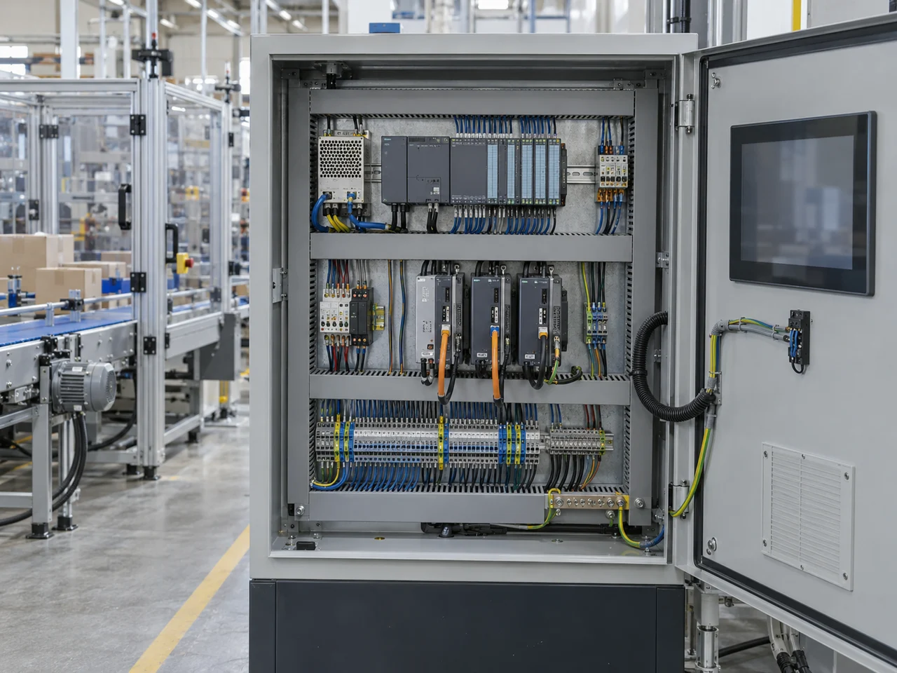
Specify the controller, its connected devices and the timing you need at the machine. This page focuses on PLC-based motion control, using Megmeet’s MC5000 family as a worked product reference—not as a specification for every industrial control system.
CNFX editorial research · Sources checked October 10, 2026 · 4 sources
Write supply tolerance, climate and input type into the order
The parameter table above asks for exact supply and temperature limits. Beckhoff's technical data for its CX7000 compact controller shows what a complete answer looks like: power supply 24 V (−15%/+20%), operating temperature −25…+60 °C, storage −40…+85 °C, relative humidity 95% without condensation, protection rating IP20, and vibration/shock and EMC conformity named by standard (EN 60068-2-6/-27, EN 61000-6-2/-4). [4]
Editorial calculation: 24 V −15% is 20.4 V and +20% is 28.8 V, so the 24 V supply and its wiring must hold the controller within that band under load. An IP20 rating means the controller goes inside an enclosure; specify the cabinet rating separately. [4]
For the integrated digital inputs the same page cites EN 61131-2 type 3, with a signal “0” of −3…+5 V, a signal “1” of 11…30 V and a configurable input filter (standard 3 ms, minimum 10 µs); outputs are rated 24 V DC, 0.5 A. Ask your supplier for the same fields — supply tolerance, IEC/EN 61131-2 input type, filter time and output current — for each CPU and I/O module in the quotation. [4]
Field
CX7000 published value
Ask for your controller
Power supply
24 V (−15%/+20%)
Tolerance and maximum current
Operating / storage temperature
−25…+60 °C / −40…+85 °C
Ratings for CPU, modules and HMI
Humidity, protection
95% no condensation; IP20
Enclosure rating for the cabinet
Digital input type
EN 61131-2, type 3; filter 3 ms standard, 10 µs minimum
Input type and filter range
02
Choose pulse-train or EtherCAT bus motion
Megmeet offers pulse-motion and EtherCAT-motion variants, with a separate motion-control CPU described in the family brochure. Select the exact controller and drive interface before counting axes. The family maximum is not a capability of every part number. [1][3]
Count the axes that must run together
List coordinated groups, cam axes and future options alongside the total. A larger CPU suffix does not prove the required group can run at the advertised minimum cycle. Ask for a demonstrated configuration with your drive models and load. A later CPU change requires a compatibility and commissioning review; it does not necessarily require wholesale rewiring. [1]
Item
Pulse motion
EtherCAT bus motion
Axis capacity
The brochure’s family headline is up to 38 pulse axes. MC5100EA has six 2 MHz differential pulse outputs; MC5000-8PO adds eight 200 kHz axes per module, with up to four modules stated. Confirm the supported CPU/configuration. [1]
MC5000 bus variants are offered for 8, 16, 32 or 64 axes. The suffix matters. [1]
Command interface
Confirm pulse mode and electrical levels at each drive. The 8PO table lists pulse/direction, forward/reverse and AB modes; one universal “pulse-and-direction pair” is not a wiring specification. [1]
Commands and status depend on the drive profile and mapped process data. ETG describes cyclic exchange and profiles including CiA 402; not every device implements every profile. [2]
Feedback and diagnostics
Specify how encoder, ready, fault and limit signals reach the controller. Pulse command wiring alone does not define the feedback architecture. [1]
Request the actual position/status objects, update rates and fault behavior in the tested drive configuration. A bus connection alone does not establish which values are exchanged. [2]
Expansion and wiring
List pulse outputs and high-speed inputs separately from ordinary I/O. Confirm terminal assignments and the expansion-module limit. [1]
Show drives and remote I/O on the topology drawing, including cable lengths and junction devices. EtherCAT supports line, tree and other topologies, not only one daisy chain. [2]
03
Follow a signal from the sensor to the machine
In Megmeet’s application diagrams, field signals reach local or remote I/O, the PLC executes the application, and pulse or bus commands reach drives. The HMI exchanges operating data over the selected communication link. The final motor, valve or other actuator is part of the machine scope and must also be identified in the order. [1]
Functional component / BOM reference
Role in the assembly
What the quotation must identify
Programmable logic controller
Runs the application and coordinates the selected motion functions.
Exact CPU, firmware and programming environment. The 202405 brochure distinguishes E, EA and EB variants; their I/O cannot be substituted by name alone. [1]
Human–machine interface
Displays operating information and accepts the configured operator commands.
HMI model, project file, communication mapping and the actions enabled for each user. The brochure shows an MZ800-series HMI in an application example, not an HMI included with every CPU. [1]
Input/output modules
Connect discrete signals and convert the specified analog or temperature channels.
Input type, output type, channel count, isolation, conversion time and terminal assignment. Analog resolution is not the accuracy of the finished control loop. [1]
Communication interfaces and remote-rack head
Connect the controller, drives, distributed I/O and supervisory equipment.
Identify integrated ports and separately supplied modules. MC5000S-ET, S-EIP and S-PN refer to different remote-rack protocols; they are not interchangeable adapters. [1]
Power-supply unit
Provides the specified electrical supply to the control hardware.
Power model, input range and a load schedule for logic, I/O and field devices. The MP50AC220 is listed as 24 V / 2 A output; the brochure disagrees internally on its AC input range. [1]
Sensors and signal connections
Provide the position, process and machine-state information used by the application.
Sensor models, ranges, output types, cables, shielding and connection drawings. The brochure illustrates a color sensor for registration; it does not specify a universal sensor set. [1]
This is a functional order checklist, not a fabrication BOM or a promise that all six items ship with the PLC. The reviewed brochure does not establish housing, PCB, terminal, display-glass or cable material grades for the complete assembly. Request model-specific declarations where the environment requires them.
04
Read the CPU model code before ordering
The table below follows the brochure’s CPU-series list on printed pages 9–10. Read both the family letters and axis suffix. High-speed capability can be a function of an existing terminal; do not add it again as extra physical I/O. [1]
CPU model
Built-in I/O
Motion
MC5200E
16 inputs / 16 transistor outputs
General main module; no EtherCAT motion-axis count in the series list. [1]
MC5100EA
Four 200 kHz pulse inputs and three 1 MHz differential inputs; four transistor outputs and six 2 MHz differential pulse outputs
Pulse-motion main module. Obtain the pin and mode allocation for simultaneous use. [1]
Eight inputs and eight outputs, each side supporting four 200 kHz high-speed channels
MC5101EB is the pulse variant; MC5001EB suffixes identify bus-axis capacity. The main table separates general and high-speed channels; do not count them twice. [1]
Program and data
The family brochure lists 320K ladder steps, 2 MB C-language capacity and 2 MB data capacity. These are different allocations, not one interchangeable memory pool. [1]
Local and remote expansion
Up to 16 local modules / 1,024 points; up to eight EtherCAT remote racks, with 16 modules per rack and 8,192 remote points stated. Request a validated module, power and cycle-time schedule rather than assuming all maxima are simultaneously achievable. [1]
Separate communication paths
The brochure lists Ethernet with seven sockets for Modbus TCP/free protocol and two RS485 ports. Identify these separately from the EtherCAT motion interface on the wiring drawing. [1]
MC5000-0064ETN is a 64-point transistor output module, not a CPU. The brochure’s unlabeled main-module dimension table must not be reassigned to that output-module code. Model-specific terminal and installation drawings remain required. [1]
05
What the EtherCAT figures mean
ETG describes EtherCAT’s design goals as cycles of 100 µs or less and synchronization jitter of 1 µs or less. Megmeet advertises a 250 µs control cycle for this family. Neither statement is a measured sensor-to-actuator response for your machine. [2][1]
Prove the drive configuration, not just the protocol name
Request the exact drive firmware, EtherCAT Slave Information file, supported drive profile and mapped process data used for acceptance. ETG lists separate communication profiles, including CoE, SoE, EoE, FoE and AoE; sharing an EtherCAT label does not establish application-level compatibility. Ordinary EtherCAT communication also does not establish a functional-safety claim: Safety over EtherCAT is a separate protocol and system consideration. [2]
Keep supervisory traffic and motion timing explicit
ETG describes optional Ethernet-over-EtherCAT mailbox tunnelling. Do not assume every device offers it, or that an ordinary Ethernet switch can be inserted into a chosen EtherCAT line without an engineered topology. Identify HMI/MES traffic and the physical interface used for it. [2]
Bus period
A configured 250 µs period corresponds arithmetically to 1 ÷ 0.00025 = 4,000 cycle opportunities per second. This does not prove that each drive receives a freshly calculated position command on every cycle. Ask for task timing, process-data mapping and drive update behavior. [1][2]
Program execution
The brochure feature text says a 100K-step standard program executes in no more than 2.2 ms, while its table says 2 ms / 100K steps. These are benchmark statements, not the measured scan time of your application. Keep that discrepancy visible when requesting a test. [1]
I/O and conversion
The family claims a 0.1 ms refresh for 16 digital I/O modules. Its analog tables separately specify conversion rates. A backplane refresh figure cannot replace input filtering, A/D conversion, application execution or actuator response in the timing budget. [1]
Clock synchronization
Distributed clocks coordinate local device events; ETG describes synchronization jitter significantly below 1 µs. Clock alignment is a different quantity from application latency or axis following error. [2]
Cable distance
ETG specifies up to 100 m between 100BASE-TX nodes, with fibre options for longer links. This is a link limit, not a 100 m limit on the entire network. Specify topology and approved junction/media devices. [2]
Network interruption
ETG’s under-15-µs figure concerns detection of a removed neighbour and closing the affected port in its hot-connect discussion. It is not a restart time or a guarantee of safe machine behavior. Define communication-loss reactions with the machine supplier. [2]
06
Specify what the assembled system must achieve
Parameter
What must be measured or specified
I/O capacity · points
Separate CPU terminals, local expansion and remote racks, then list actual module codes and power demand. The family maxima are not a delivered configuration. [1]
Processing speed · ms
State the program and test conditions. The brochure gives both 2 and ≤2.2 ms for its 100K-step benchmark; neither is your machine’s complete response. [1]
Communication protocols
Name the interface, role and device profile: EtherCAT motion/remote I/O, Ethernet Modbus TCP, or RS485, as applicable. A protocol list without the matching ports and roles is insufficient. [1][2]
Operating temperature · °C
Obtain the exact CPU, module, HMI and enclosure limits. The brochure’s analog accuracy test temperatures do not establish an ambient rating for the complete system. [1]
Supply · V AC/DC
The MP50AC220 series list says 100–240 VAC input; its power-specification table says 110–240 V, with 24 V / 2 A output. Confirm the ordered unit’s current manual and nameplate; neither range establishes every device’s DC tolerance. [1]
Control accuracy
Separate sensor error, analog-conversion accuracy and the process or axis acceptance criterion. Do not assign one “% of span” figure to the entire assembly or treat bit resolution as accuracy. The brochure reports individual module characteristics. [1]
Scan time · ms
Record the actual application task period and its variation under the agreed load, including communication and enabled functions. Keep it separate from the minimum bus synchronization period. [1][2]
Memory
Specify ladder steps, C-program capacity and data allocation separately; also obtain retention, project/version and backup requirements for the selected firmware. [1]
Ingress protection
Request the rated CPU/module/HMI and enclosure surfaces separately. The reviewed sources do not establish a protection rating for the assembled panel.
Mounting
Obtain the selected models’ installation drawings, clearances, grounding and enclosure requirements. The brochure’s product pictures do not establish a universal rail/panel/rack mounting choice. [1]
Weight · kg
Request the exact controller and assembled-panel weights. The weight of one controller is not the shipping weight of an assembled cabinet.
Dimensions · mm
Require labeled width, height and depth for each module plus the assembled layout and cable clearances. Do not convert the brochure’s generic main-module drawing into a size for every MC5000 item. [1]
07
List every module in the quotation
The family catalogue establishes these module options. Match each part number to its signal, rack and power requirements; the presence of a catalogue entry is not a confirmed delivery commitment. [1]
Digital I/O: input, relay/transistor output and mixed modules. Counts vary; the MC5000-0014EPN-P is a 14-point high-side-output exception to a “16–64 points” shorthand. [1]
High-speed: MC5000-1616ETN-PH is listed with four high-speed counter channels. MC5000-8PO offers eight 200 kHz pulse axes, with up to four modules stated; confirm CPU support, modes and terminal mapping. [1]
Analog and temperature: select actual 4/6/8-channel analog-input, four-channel analog-output, four-channel RTD or 4/8-channel thermocouple modules. Range, resolution, conversion time, isolation and calibration are separate fields. [1]
Remote racks: order the protocol-specific head—MC5000S-ET for EtherCAT, S-EIP for EtherNet/IP or S-PN for PROFINET—and the compatible modules and power supply. [1]
Power and connection hardware: itemize the power module, cables and terminal blocks. Resolve the MP50AC220 input-range conflict before accepting a mains specification. [1]
Availability: the brochure marks MC5000-2WT with an asterisk meaning “developing.” Do not promise a supplied weighing module from that 202405 entry without current manufacturer confirmation. [1]
08
Keep a recoverable configuration with the machine
The brochure describes Flash storage without battery maintenance, programming tools and diagnostics. That does not replace a machine project backup or define a maintenance interval. Obtain the supplier’s current service procedure for the assembled control system. [1]
At acceptance, retain the CPU/HMI project versions, drive parameters, ESI files, module list, terminal drawings and the agreed timing-test record.
Agree tests for the actual coordinated axes, representative I/O load and communication-loss reactions. State which observations demonstrate the required operating behavior.
For troubleshooting, preserve the configuration and diagnostic record before changing settings. ETG describes working-counter and communication diagnostics; these are diagnostic evidence, not a safety certification. [2]
Before replacing a CPU, drive or I/O module, have the supplier confirm the hardware/firmware and project compatibility, restoration steps and required recommissioning. Follow the machine’s isolation and service procedure; an advertised online-edit feature is not permission to alter a running machine. [1]
09
Define the delivered control system and the test it must pass
Paste it into your enquiry below or into an email to a maker, then replace every bracket.
Machine/function [ ]; quantity [ ]; controller-only or assembled-system scope [ ]
CPU exact model [ ]; hardware/firmware [ ]; programming tool/version [ ]
Servo/stepper models and firmware [ ]; axes [ ]; coordinated groups/cams [ ]; reserve [ ]
Pulse modes/levels or EtherCAT profile and ESI files [ ]
Required bus/task periods [ ]; sensor-to-actuator response criterion and test load [ ]
Digital I/O types/counts [ ]; analog ranges/accuracy/conversion [ ]; RTD/TC channels [ ]
Local and remote module codes, rack heads and topology drawing [ ]
HMI model/project and supervisory protocols/port assignments [ ]
Power supplies and separate logic/field-device load schedule [ ]
Environment, enclosure protection, mounting, layout and cable clearances [ ]
Communication-loss behavior and applicable machine-safety scope [ ]
Project/parameter backup, licences, access, restoration and service documents [ ]
Acceptance test, applicable declarations and model-specific supporting documents [ ]
Destination [ ]; delivery date [ ]; confirmed module availability [ ]
Separate controller supply from integration and components
Megmeet publishes the PLC family discussed here; LIENM describes automation-system work.
Shenzhen Megmeet Electrical Co., Ltd.
Shenzhen (published company offices; order manufacturing site unconfirmed)
Publishes the MC5000 PLC and motion-control family with CPU and expansion-module model lists. Request the exact CPU, tested drives, firmware and module schedule; a group product page does not identify the manufacturing site or certify the complete machine.
Its cosmetic-processing equipment site lists Automation Control Systems and describes BAS/GMS/PWS work. This supports an integration enquiry, not a claim that LIENM manufactures the MC5000 or has validated a particular EtherCAT drive combination. Define responsibility for programming, panel supply and commissioning.
Explore company information and manufacturing capabilities, then discuss the scope of your project with a relevant supplier.
Share this page
Compiled and source-reviewed by the CNFX editorial team.
Scopes are based on the opened company pages, not factory audits, product certification or an integration acceptance test. How we source and review
· Page last updated 13 October 2026
Buyer questions
Pulse or EtherCAT motion control?
Choose against the required drive interface, coordinated motion, feedback and diagnostics. The MC5000 family includes pulse variants and bus models with up to 64 EtherCAT axes, but that maximum does not describe every CPU. Request a tested model/firmware and I/O configuration. [1][2]
How fast is EtherCAT?
ETG describes design goals of cycles at or below 100 µs and synchronization jitter at or below 1 µs. A controller’s configured bus period, PLC program timing and measured machine response are distinct. Megmeet’s 250 µs family claim must be checked at the intended axis count and load. [2][1]
How long can an EtherCAT cable be?
ETG gives up to 100 m between 100BASE-TX nodes, not for the entire network. Longer links require suitable media, such as fibre, and compatible devices. Confirm the complete topology and cable specification. [2]
Is MC5000-0064ETN a CPU?
No. In Megmeet's 2024 brochure it is a 64-point transistor output module. [1]
What environmental and supply data should a PLC datasheet give?
Beckhoff's CX7000 technical data is one example: 24 V supply with −15%/+20% tolerance, −25…+60 °C operation, 95% humidity without condensation, IP20, and inputs to EN 61131-2 type 3. Ask for the same fields for your controller. [4]
Sources and what still needs a direct check
Sources checked 2026-10-10. Standards bodies and regulations define the requirements; manufacturer pages show published ranges for those models only. CNFX does not certify products or suppliers.
Tested CPU/firmware, drive/ESI combination and usable cycle at the full axis and I/O load.
MP50AC220 input range: 100–240 VAC in the series list versus 110–240 V in the power table.
Application execution measured on the actual project; brochure benchmark text says ≤2.2 ms while its table says 2 ms / 100K steps.
Exact installation, environmental, enclosure and material declarations. The official E/EA English quick-start download links returned expired-signature responses during this review; unavailable manuals are not treated as verified.
Current availability of items marked developing in the 202405 brochure, including MC5000-2WT; complete machine safety and compliance evidence are outside these catalogue claims.
Buyer enquiry
Request manufacturing insight
for Industrial Control Systems
Ask for use case, specification boundaries, supplier type, and RFQ preparation
information for this product.
Where it goes
Straight to the CNFX editorial desk, and to the manufacturer if this product is
linked to a claimed profile. Nothing is broadcast to a supplier list.
Your details stay here
We do not sell or rent enquiry data, and we do not add you to a mailing list.
Used only to answer this request.
No commission, no middleman
CNFX is a directory. We take no cut of any order and never negotiate on a
supplier's behalf.
What to include
Share your product specifications, quantity, destination and target delivery date.
Need to Manufacture Industrial Control Systems?
Compare manufacturer profiles with relevant product and process capability.