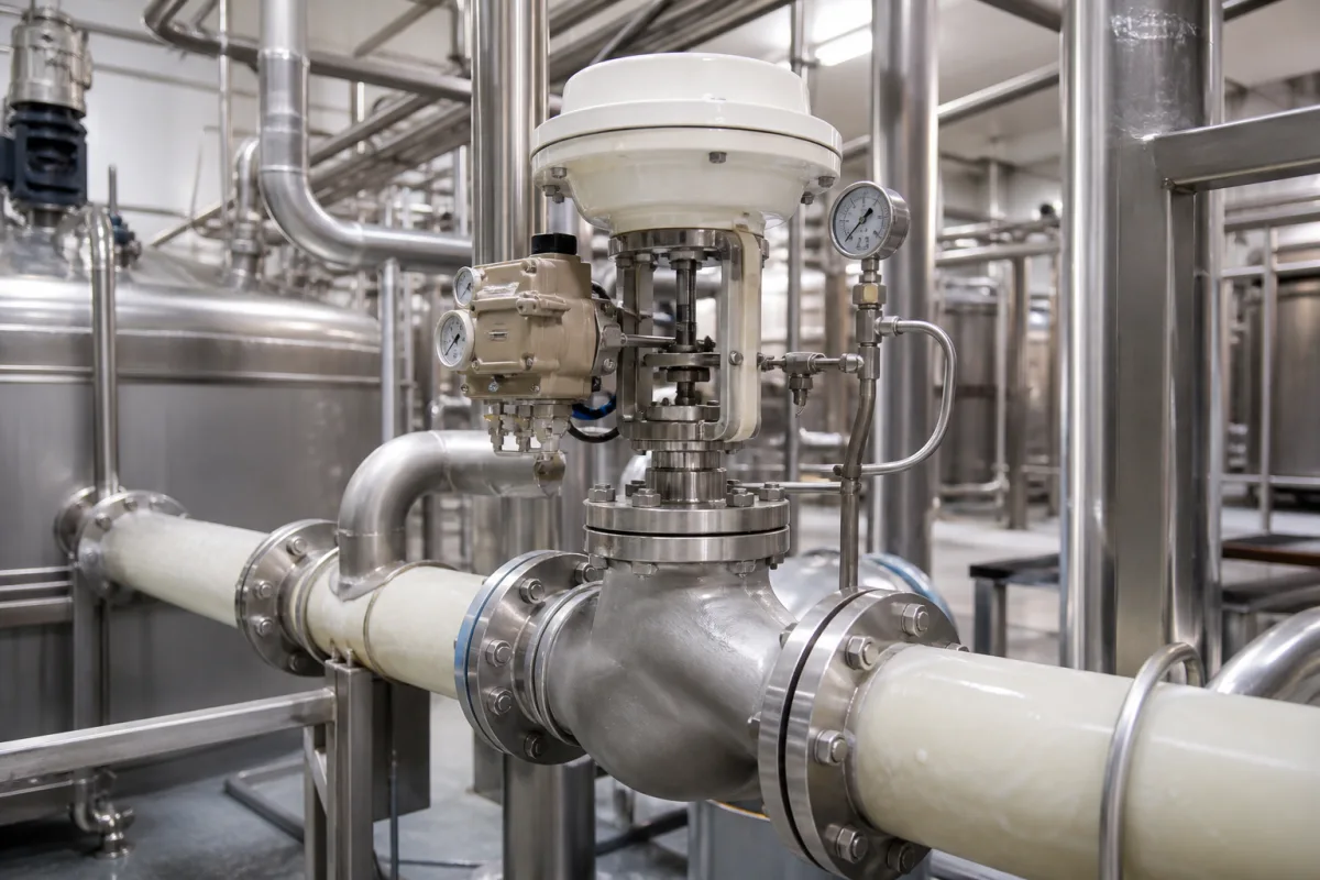
Starch slurry pressure control valve for hydrocyclone washing stations: holding feed pressure on starch milk
Starch milk service · a pneumatic globe valve that holds the feed pressure, or the pressure drop, of a starch washing hydrocyclone station
In corn and wheat wet milling the starch is washed and concentrated in banks of small hydrocyclones, and the pressure at their inlet decides which particles leave with the starch underflow and which go to the protein-rich overflow. The valve on this page is the one that holds that pressure on starch milk: a globe body with a diaphragm actuator and positioner, flanged into the stainless line, throttling a suspension of starch granules that ranges from dilute feed to a heavy underflow. Two questions decide the order: which pressure, or pressure drop, the valve must hold and how closely, and what trim survives throttling a solids-laden liquid at that differential.
Pneumatic globe control valves on starch milk lines in wet-milling plants that hold hydrocyclone feed pressure, station pressure drop or recirculation flow, with their trim, actuator, positioner and gauge connections. General-purpose pneumatic globe control valves, their seat size, flow coefficient and shut-off class are covered on the Pneumatic globe control valve page; hygienic regulating valves for dairy, beverage and pharmaceutical lines are covered on the Hygienic pneumatic regulating valve page; Kvs-scale micro-flow dosing valves on the Low-flow pneumatic flow control valve page; loose plugs and trim parts on the Control valve plug page; boiler feedwater cages on the Feedwater control valve trim page. The cyclones themselves are covered on the Continuous starch hydrocyclone separator page; pumps and centrifuges are outside this page.
CNFX editorial research · Sources checked October 12, 2026 · 4 sources
Which pressure the valve holds: cyclone pressure drop, inlet band and the energy cost of each bar
A 1983 Dorr-Oliver patent application states that the volute hydrocyclones then in use in the starch industry, about 10 mm across the wider end of the vortex chamber, were operated at a pressure drop of 6 to 6.5 bar, against 3 to 3.5 bar for older-type cyclones of the same size and throughput. Its own test at a 4 bar pressure drop gave throughput and starch recovery values that it calls insufficient. [1]
The same document prices that pressure: in a nine-stage maize starch washing installation, the additional 3 bar of feed pressure represents about 5 kWh per tonne of processed maize. [1] Editorial note: a valve that throttles the pump discharge down to the station setpoint is spending some of that pump head as well, so the pressure the valve itself drops at design flow is worth stating in the enquiry rather than leaving to the pump margin.
A University of Illinois laboratory study run with a single 10 mm cyclone set the inlet pressure at 8.96–9.65 bar (130–140 psi). Above 9.65 bar, larger protein particles were thrown into the starch fraction; below 8.96 bar, smaller starch particles went to the protein fraction. The authors call setting the inlet pressure the only critical point of their procedure, and they held it by recirculating part of the pump flow back to the feed tank rather than by throttling the outlets, whose valves stayed open during testing. [2] Editorial calculation: the band is 9.65 − 8.96 = 0.69 bar wide, about ±3.7% around its 9.3 bar midpoint; a positioner and pressure loop for this duty have to hold the setpoint inside a window of that order, at laboratory scale.
Tell the valve supplier whether the loop controls inlet pressure, pressure drop across the station, or a recirculation flow back to the feed tank, and give the setpoint, the allowed band and the pump curve.
02
Trim for throttling starch milk: hardened seats, full-contour plugs and the differential at which they are needed
Valtek's sizing and selection manual lists the presence of abrasive solids among the five process conditions that wear valve trim, alongside gas versus liquid, velocity and pressure differential, temperature and flashing. It adds that, with liquids, cavitation can erode even hardened trim. [3]
Its Table 10-I gives the differential pressure above which hardened trim is anticipated, by inner-valve size. Valtek adds that above 1.5 times these values full-bore and full-contour hardened trim is recommended, and it applies one general rule: hardened trim is considered for all choked-flow conditions. [3] Editorial calculation: 6.5 bar is about 94 psi. Under the manual's general process-fluid column that is above the 75 psi throttling threshold for 4–6 inch trims and the 50 psi threshold for 8–12 inch trims, below the 150 psi threshold for 2–3 inch trims; at 8–12 inch it is also above 1.5 × 50 = 75 psi, where full-bore, full-contour hardening applies. The table does not name starch, so treat this as a starting point for the supplier's own selection.
The manual's standard trim is 316 stainless steel, which it rates fair for erosion and abrasion at Rockwell C 8. Stellite No. 6 hardfacing, the material it stocks for hardened trim, is rated good at Rockwell C 44; 440C stainless at 55–60 and tungsten carbide at 72 are rated excellent, with the manual warning that 440C is dimensionally unstable in heat treatment and prone to cracking, so 300-series seat rings with Stellite seat surfaces are its alternative. [3]
Ask which surfaces are hardened (seat surface, full seat-ring bore, full plug contour, lower guide), the hardfacing or solid material, and whether the supplier's selection was made for a solids-bearing liquid at your pressure drop.
03
Flow and hygiene of the washing unit the valve serves
SiccaDania's data sheet for its Hydro hygienic cyclone, a multi-stage counter-current starch washing unit, gives the flow range the control valve has to pass: maximum feed capacity rises from 14 m³/h on the HCH 300 to 30, 49 and 71 m³/h on the HCH 400 to 600 and 100 m³/h on the HCH 700, the same for 10 mm and 15 mm cyclones. [4]
The same sheet describes the unit as full stainless steel and cleaned in place, and lists a pressure indicator among its spare parts with the mechanical seals, cyclonettes, housing seals and O-rings. [4] A valve on this line therefore has to accept the CIP chemicals and temperatures of the station and has to sit near a pressure gauge connection that operators read against the controller.
In the laboratory rig the underflow and overflow lines each carried a valve, both left open, and the rig carried pressure gauges at the cyclone. [2] The Dorr-Oliver document explains why the pressure matters so much: a volute cyclone needs a higher feed pressure because faster rotation inside the vortex resists the entry of the feed stream; feeding at lower pressure lowers the input energy, the kinetic energy in the critical regions of the vortex and the throughput. [1]
Give the station model or the number of stages, the maximum and minimum feed flow, slurry density at the valve, the CIP chemicals and temperature, and where the pressure transmitter and gauge sit relative to the valve.
04
Data for a starch milk pressure control valve
Paste it into your enquiry below or into an email to a maker, then replace every bracket.
Duty: [inlet pressure, station pressure drop or recirculation; setpoint and allowed band]
Flow: [maximum and minimum m³/h; pump curve]
Slurry: [density °Bé at the valve; temperature; pH]
Pressure drop across the valve: [at maximum and minimum flow]
Trim: [hardened surfaces; hardfacing or solid material]
Body: [size; flanges; stainless grade]
Actuation: [diaphragm actuator; positioner; fail position; air supply]
Cleaning: [CIP chemicals and temperature]
Explore company information and manufacturing capabilities, then discuss the scope of your project with a relevant supplier.
Share this page
Compiled and source-reviewed by the CNFX editorial team.
Each manufacturer above links to the page on that company's own website where the product is listed, with the date we checked it. How we source and review
· Page last updated 13 October 2026
Buyer questions
What pressure do starch washing hydrocyclones run at?
A Dorr-Oliver patent application states 6–6.5 bar pressure drop for the 10 mm volute cyclones in starch industry use, against 3–3.5 bar for older types; a University of Illinois lab rig held its inlet at 8.96–9.65 bar. [1][2]
What happens if the inlet pressure drifts?
In the University of Illinois study, pressure above 9.65 bar sent larger protein particles into the starch, and pressure below 8.96 bar sent smaller starch particles into the protein fraction. [2]
When does the valve need hardened trim?
Valtek's manual gives differential thresholds by trim size, for example 75 psi throttling for 4–6 inch trims on general process fluids, and says hardened trim is considered for all choked-flow conditions. [3]
How much flow does a starch washing unit take?
SiccaDania lists maximum feed capacities from 14 m³/h (HCH 300) to 100 m³/h (HCH 700). [4]
Sources and what still needs a direct check
Sources checked 2026-10-12. Pressure figures for starch hydrocyclones come from a Dorr-Oliver patent application and a peer-reviewed University of Illinois study; trim thresholds from Valtek's sizing manual; station flows from a SiccaDania data sheet.