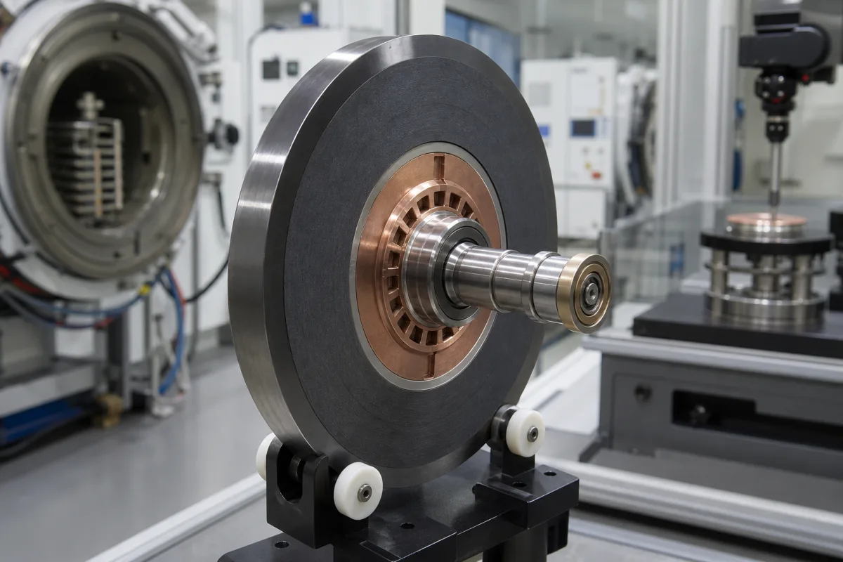
Medical X-ray tube anode assembly: brazing the graphite heat-storage back to the TZM plate and coating it to radiate heat
How the rotating target inside a medical tube insert is joined and finished · brazes that keep TZM below its recrystallisation temperature, barrier layers against brittle carbide, and emissive coatings outside the focal track
A medical X-ray tube anode assembly is the spinning target inside the vacuum insert: a disc of molybdenum alloy carrying a tungsten-rhenium focal track, a block of graphite brazed behind it to store heat, a stem, and the rotor that the stator drives. Since only about 1% of the electrical energy reaching the anode leaves as X-rays and the rest is heat, how the layers are chosen, joined and coated decides how much load the target accepts and how long the joint survives thermal cycling.
The joined construction of rotating anode assemblies for medical X-ray tube inserts (CT, radiography and fluoroscopy): the braze joint between the graphite heat-storage back and the TZM or other molybdenum-alloy plate, barrier and intermediate layers, emissive coatings outside the focal track, and the stem and rotor as a built subassembly. Choosing a target disc by tube load, anode angle, rotation speed and the IEC tests the tube faces is covered on the Tungsten-rhenium target disk page. Complete rotating-anode tubes, inserts and tube housing assemblies are covered on the X-ray tubes and tube assemblies page; generators, collimators, detectors and complete X-ray systems are outside this page.
CNFX editorial research · Sources checked October 12, 2026 · 3 sources
Brazing graphite to TZM below about 1400 °C: two-step Ti-Cr-Be or Ti-Si joints and a niobium barrier
GE Medical Systems' US 6,421,423 explains the conflict: the TZM substrate is forged for strength, but brazing the graphite heat sink can need up to 1900 °C, while TZM recrystallises near or above 1400 °C and loses its elevated-temperature yield strength. [2]
Its answer for CT targets is two brazes. First a thin molybdenum alloy sheet, preferably about 0.5 mm thick, is brazed to the graphite disc with pure zirconium or pure titanium. Then this plated graphite is brazed to the TZM cap with either a Ti-Cr-Be alloy (about 72 parts titanium, 25 chromium and 3 beryllium by weight, liquidus about 1110 °C) or a Ti-Si alloy (about 91.5 parts titanium and 8.5 silicon, liquidus about 1200 °C). Molybdenum diffusing into the joint raises its remelt temperature to approximately 1700 °C, above the TZM recrystallisation point. [2]
Philips tackles a different failure: conventional joints form a Ti+TiC eutectic layer that initiates cracks. Its method puts a barrier layer such as niobium, tantalum or platinum between the graphite and the braze; the barrier must melt above the brazing temperature (for example above 1700 °C) and not form a brittle carbide. With titanium, which melts at about 1600 °C, the result is a thicker ductile pure-titanium layer and no eutectic layer subject to void formation. [1]
Editorial calculation: GE's braze liquidus of about 1110 °C sits roughly 290 °C below the stated 1400 °C recrystallisation temperature, and the Ti-Si alloy at about 1200 °C roughly 200 °C below it. [2]
Ask which braze system joins the graphite to the plate, the brazing temperature the TZM sees, whether a barrier or intermediate sheet is used, and what thermal-cycling or bond tests the joint has passed.
02
A 90–95% tungsten, 5–10% rhenium track on an 8-inch TZM plate with a graphite back up to 2 inches thick
Philips' US 9,053,898 describes X-ray anodes made on a molybdenum alloy substrate such as TZM, with a tungsten-alloy focal track that it puts at 90–95% tungsten and 5–10% rhenium, and states that the targets are brazed to a graphite back for additional heat storage. For CT, the anode plate is about 8 inches in diameter and about ¾ inch thick, and the annular graphite piece, of similar diameter, is between ½ inch and 2 inches thick. [1]
In the same patent, electrons accelerated across 200,000 volts heat the anode assembly to between 1100 °C and 1400 °C, and part of the beam reflects from the focal spot and scatters inside the evacuated chamber. [1] Schwarzkopf Technologies' US 4,516,255 puts the energy balance at about 1% converted to X-rays and 99% to heat, and defines TZM as about 0.5 to 1.5% titanium, about 0.5% zirconium and optionally about 0.3% carbon by weight, the rest molybdenum. [3]
Editorial calculation: 8 inches is about 203 mm and ¾ inch about 19 mm; a graphite back of ½ to 2 inches is about 12.7 to 50.8 mm, so on the dimensions Philips gives, the graphite can be up to roughly 2.7 times as thick as the metal plate it supports (2 / 0.75).
State the tube type the assembly is for, plate diameter and thickness, focal track alloy and thickness, graphite grade and thickness, and the heat storage the tube maker specifies for the target.
03
Oxide coating outside the focal path over a 10–200 µm molybdenum or tungsten interlayer
Schwarzkopf Technologies' patent notes that oxide coatings added to TZM anodes to raise thermal emissivity lose their good emission after a short time in operation, which it attributes probably to carbon diffusing from the carbon-containing substrate into the oxide layer. [3]
Its patent places a layer of molybdenum and/or tungsten between the TZM and the oxide coating outside the focal path. The abstract and detailed description give 10 to 200 µm, preferably 40 to 50 µm, applied by flame or plasma spraying after sand blasting, with less than 10 µm ineffective and more than 200 µm uneconomical; the summary states 10 to 100 µm, so confirm which range a supplier works to. Coatings named include TiO2, Al2O3 and ZrO2, and an anneal in hydrogen at 1600 °C for about half an hour is preferred after each coating. In its comparison, two anodes of like dimensions, one with a 10 µm molybdenum interlayer under TiO2 and one without, were each run for 500 exposures on an X-ray tube test stand. [3]
Ask for the coating material and area, interlayer metal and thickness, spraying method and post-anneal, and emissivity data after a stated number of exposures.
04
Layer stack of a CT anode target with published dimensions and temperatures
Explore company information and manufacturing capabilities, then discuss the scope of your project with a relevant supplier.
Share this page
Compiled and source-reviewed by the CNFX editorial team.
Each manufacturer above links to the page on that company's own website where the product is listed, with the date we checked it. How we source and review
· Page last updated 13 October 2026
Buyer questions
What is the focal track of a rotating anode made of?
Philips' patent gives a tungsten alloy track of 90–95% tungsten and 5–10% rhenium on a molybdenum alloy (TZM) substrate. [1]
Why is graphite brazed to the back of the anode?
For additional heat storage capacity; Philips gives a graphite piece ½ to 2 inches thick behind an 8-inch CT anode plate. [1]
Why does the braze temperature matter?
GE notes that brazing can reach 1900 °C while TZM recrystallises near 1400 °C and loses strength; its brazes melt at about 1110 or 1200 °C and remelt near 1700 °C after molybdenum diffusion. [2]
Why put a metal layer under the emissive coating?
Schwarzkopf Technologies found that oxide coatings on TZM lose emissivity in service; a 10–200 µm molybdenum or tungsten interlayer is its remedy. [3]
Sources and what still needs a direct check
Sources checked 2026-10-12. All three sources are granted US patents from anode and tube makers: Philips on niobium-barrier brazing, GE Medical Systems on two-step brazing for CT targets, and Schwarzkopf Technologies on emissive coatings over a metal interlayer.