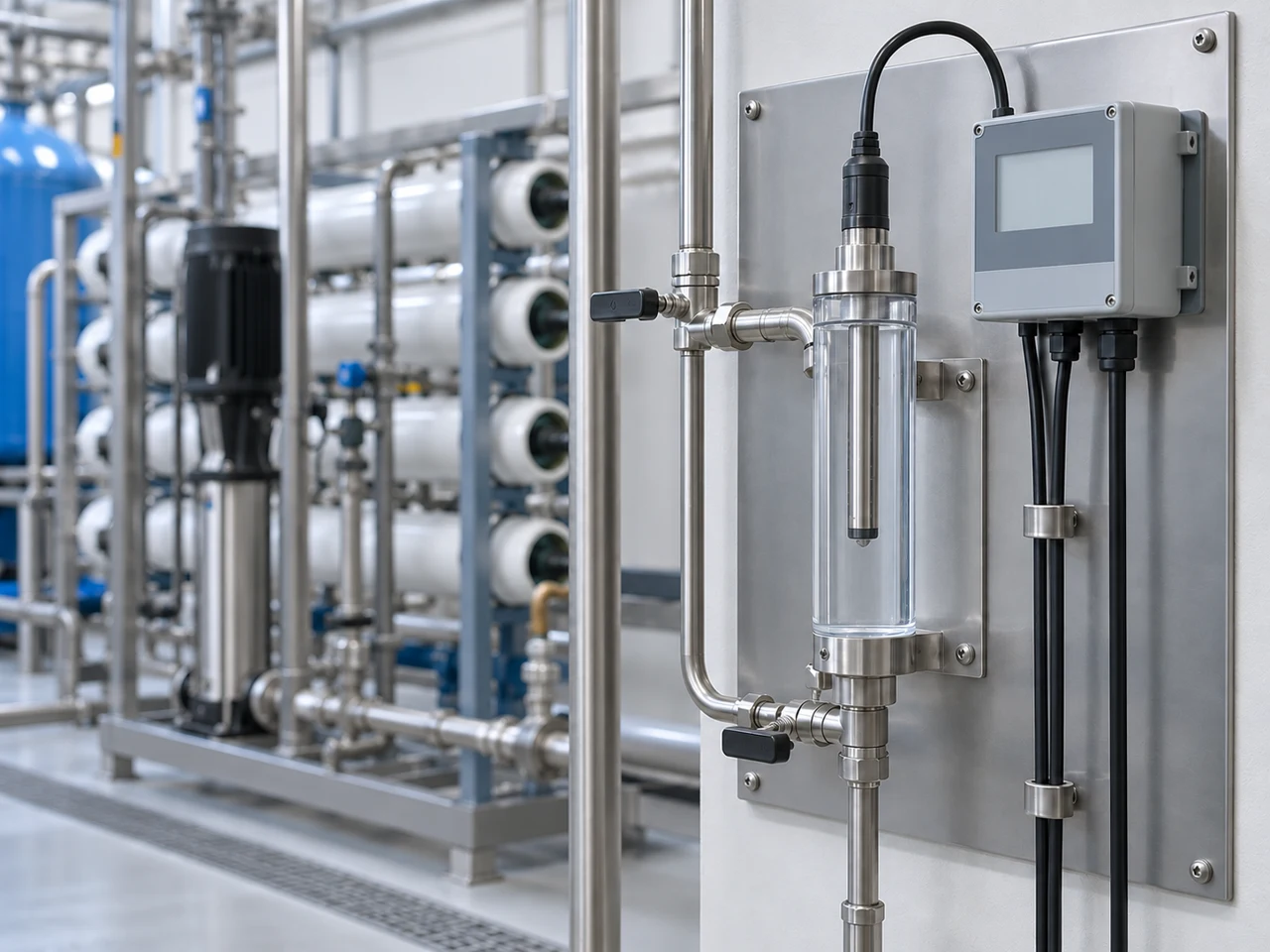
Conductivity cells: match the probe, water and transmitter
Water and process analytics · Buyer's guide
Start with the lowest conductivity you need to resolve, the process chemistry and the actual probe–transmitter pair. A controller’s wide display range cannot extend a cell’s verified measuring range, and a temperature input specification does not establish the probe’s pressure or temperature rating.
CNFX editorial research · Sources checked October 10, 2026 · 4 sources
Keep the sensing surfaces, insulation and signal path distinct
A contacting sensor uses electrodes exposed to the liquid and an alternating electrical excitation; the measured electrical response is converted using the cell constant. An inductive sensor is a different construction with encapsulated coils. This page’s BOQU example is the contacting, double-cylinder design. [4][1]
Component / BOM reference
Role in the measurement
Published construction and open detail
Electrodes
Provide the conductive surfaces in contact with the sample; geometry and the liquid between them establish the measurement cell. [3]
DDG-1.0 prose identifies titanium alloy; its table also lists SS316L. The platinum K = 10/30 paragraph concerns other options. Obtain the selected electrode material and calibration constant. [1]
Body, insulating separation and process connection
Hold the electrode geometry and mount the probe into its process or flow fitting. The mounting arrangement must allow the sensing area to remain wetted. [3]
The DDG-1.0 page gives 1/2 or 3/4 NPT, but no complete body/insulator/seal material schedule. Do not assume glass, PVC, PTFE or stainless steel from a generic component list. [1]
Cable and connector / terminal interface
Carry the electrode and temperature signals to the compatible transmitter. The DDG-2080X manual provides electrode wiring diagrams. [2]
The cited sensor page does not specify cable length, jacket material or connector protection. Request the actual wiring and cable specification; cable-related effects can influence conductivity measurements. [4]
Temperature element, when ordered
Measure sample temperature for the instrument’s compensation function; correct element selection is required in automatic mode. [2]
BOQU lists NTC 2.252K, 2K, 10K, 20K, 30K, Pt100 and Pt1000 alternatives. The cited DDG-2080X accepts Pt1000 or NTC30K. The alternatives are not all fitted in one probe. [1][2]
Functional component reference, not a manufacturing BOM with quantities or spare-part numbers. The flow fitting and controller are separate items unless included in the order. Conductivity responds to combined ionic content; it does not identify which ion is present. [4]
02
Choose K for the conductivity range, then use the calibrated value
The cell constant represents the electrode geometry. METTLER TOLEDO recommends lower constants for low-conductivity water and higher constants for more conductive samples; the transmitter needs the actual cell constant. BOQU’s DDG-1.0 table below describes one nominal K = 1.0 option, not every conductivity application. [3][1]
A pure-water application label is not a low-end accuracy result
BOQU advertises pure and ultrapure-water use, but the DDG-1.0 table does not state cell-constant tolerance or accuracy near ultrapure-water conductivity. Establish the required low-end uncertainty with the selected transmitter and calibration evidence; a range starting at zero does not prove useful resolution there. [1][3]
Do not turn a broad corrosion claim into a compatibility table
BOQU makes a broad titanium corrosion-resistance claim with an exception worded “fluoride acid”. It does not provide a concentration/temperature compatibility chart for the complete sensor. Give the supplier the actual chemicals, concentrations and cleaning conditions, and obtain compatibility for electrodes, insulators, seals and connections. The wording does not establish one rule for every fluoride-containing solution. [1]
K = 30 is outside the cited controller’s entry range
The DDG-2080X manual specifies a cell-constant range of 0.001–20.000. Thus the K = 30 option mentioned on the sensor page cannot simply be entered in that cited controller configuration. Match the full order codes and current manual before combining them. [2]
Published BOQU option
What the source establishes
What remains to select
DDG-1.0, nominal K = 1.0
0–2,000 µS/cm; working pressure 0.3 MPa; 1/2 NPT or 3/4 NPT. The prose describes a double-cylinder titanium-alloy design and the table lists SS316L or titanium alloy. [1]
Obtain the actual calibrated K, minimum useful measurement level, pressure/temperature envelope and wetted-material drawing. The website’s material row is mislabeled “Pressure”; it does not identify all wetted parts.
K = 10 or 30 options mentioned in the same page
The separate paragraph describes large-area platinum electrodes for applications such as wastewater and seawater treatment. [1]
No complete model table for these options is supplied there. Do not apply DDG-1.0’s range, pressure or connection values to them.
03
Match the temperature input and measurement range before ordering
The following values belong to the BOQU DDG-2080X controller manual, not to the pressure-bearing DDG-1.0 probe. Page references below use the manual’s printed page numbers; the cover is not counted. [2]
Specify the temperature element on both orders
BOQU lists NTC 2.252K, 2K, 10K, 20K and 30K, Pt100 and Pt1000 temperature-compensation elements for the DDG-1.0, specified by the user; the DDG-2080X manual identifies only Pt1000 and NTC30K. Select the matching probe and instrument setting. The manual warns that automatic temperature mode without a connected probe will not display correctly. [1][2]
A full-scale error becomes large relative to a small reading
Illustration: if the stated ±1% F.S. applies to a selected 2,000 µS/cm full scale, the absolute error term is ±20 µS/cm. Relative to a 100 µS/cm reading that is ±20%. This arithmetic illustrates the range choice, not a measured DDG-1.0 system error; confirm the manufacturer’s full-scale basis and the other uncertainty contributions. [2]
Controller item
Published value
How to apply it
EC ranges
Selectable 0–20 / 200 / 2,000 µS and 0–20 / 200 / 2,000 mS ranges, printed p.21. [2]
The manual abbreviates the conductivity units without “/cm”. Confirm the unit and selected range on the supplied instrument; none of these settings extends DDG-1.0’s stated 0–2,000 µS/cm range. [1]
Accuracy / resolution
±1% F.S.; resolution 0.01 / 0.1 / 1 in the specifications, p.3. [2]
Full scale and display resolution are different quantities. Obtain the applicable range basis and the uncertainty of the complete calibrated probe–instrument pair.
Temperature input
Pt1000 or NTC30K; −10 to +130 °C; ±0.2 °C, p.3. [2]
These are controller input specifications. They do not establish the installed probe’s allowable process temperature or pressure.
Compensation settings
Solution coefficient setting 0.01–40.00%; reference temperature 15–35 °C, p.19. [2]
The manual labels the coefficient in percent without spelling out its per-degree unit here. Confirm the compensation convention and the appropriate coefficient for the actual solution.
Analog outputs
Two isolated 4–20 mA outputs; maximum 500 Ω load; ±0.05 mA output accuracy, p.3. [2]
The measurement and temperature outputs have separate scaling. Changing the analog-output span does not by itself select a narrower EC input range.
Relays / communication
Three relays; maximum contact rating 5 A at 250 VAC or 30 VDC; RS485 Modbus RTU. [2]
Use the actual wiring and load requirements. The manual discusses contact protection for different load types; the maximum rating is not a universal load approval.
04
Keep the sensing area wetted and let bubbles escape
METTLER TOLEDO’s Thornton FAQ explains that flow can change the sample presented to the cell even though conductivity is not intrinsically a flow measurement. Its recommendations are installation guidance, not a DDG-1.0 flow rating. [3]
Flow velocity
The FAQ offers 0.3–3 m/s as a rule of thumb, subject to the installation effects it describes. Confirm the allowed velocity and pressure loss for the actual probe and fitting. [3]
Bubbles
Air adhering to the electrodes changes the effective cell geometry and can cause unstable readings. Orient the flow path so bubbles can rise out through the outlet. [3]
Low flow and sampling delay
Dead legs and new pipe surfaces can contaminate high-purity samples; a low-flow side stream delays the response to process changes. Check sample-line routing and transit time. [3]
High flow / pressure drop
The FAQ warns that very high flow and a large local pressure drop can cause cavitation, erratic readings and possible damage. More flow is not always a correction for drift. [3]
Storage and re-wetting
METTLER TOLEDO allows its conductivity cells to be stored dry after appropriate cleaning, then fully wetted for measurement. Follow the selected BOQU probe’s instructions; this statement is not a storage rule for every sensor type. [3]
05
Keep probe ratings separate from controller specifications
The following fields describe the item being purchased. Fill an unknown from the selected probe’s current drawing or data sheet, rather than borrowing a number from the DDG-2080X instrument.
Field
Verified value or required unit
Purchasing condition
Cell constant
Nominal K = 1.0 for DDG-1.0; convention cm⁻¹
Obtain the individual calibrated value and uncertainty. Nominal geometry alone is not the calibration certificate. [1][3]
Measuring range
DDG-1.0: 0–2,000 µS/cm
Require performance at the lowest required reading, with the chosen transmitter and temperature compensation. [1]
Accuracy
Probe / system uncertainty required
The sensor page gives no accuracy figure. The controller’s ±1% F.S. is not “percent of reading” and not the complete system specification. [1][2]
Operating temperature
Probe limit in °C required
Request the probe’s temperature–pressure envelope, including cleaning conditions. Do not apply the controller’s −10 to +130 °C input range to the probe. [2]
Operating pressure
DDG-1.0: 0.3 MPa stated
Confirm the reference pressure convention and temperature conditions. A generic 1.6 MPa limit is not supported for this cell. [1]
Electrode material
Titanium alloy / SS316L options in the DDG-1.0 source
Identify the supplied option and fluid compatibility. Platinum is described for other K options; electrode material alone does not establish measurement accuracy. [1]
Body / seal material
Complete wetted-material list required
The cited table does not identify the body, insulators and seals separately; obtain that schedule for the process and cleaning fluids. [1]
Cable length
m; selected cable and wiring required
The sensor page does not give a cable-length limit. Match the wiring diagram and allowed cable to the transmitter; do not assume a universal extension length. [2]
Process connection
1/2 NPT or 3/4 NPT listed
Select one connection and obtain the fitting/insertion drawing. These are alternatives, not an assurance that both are fitted. [1]
Ingress protection
Probe/connector IP designation required
The manual’s IP65 belongs to the DDG-2080X instrument. It does not certify the probe or its cable connector for immersion. [2]
Weight
Probe mass in kg required
No probe weight is stated in the cited product table. The controller manual’s 0.85 kg is a different item. [1][2]
06
Choose the calibration method for this cell and control the outputs
Calibrate the cell constant and temperature channel as distinct checks. METTLER TOLEDO’s pure-water recommendations describe Thornton sensors and their calibration system; the BOQU controller has its own calibration mode and limits. Do not merge the two into a universal procedure. [3][2]
Calibration mode can hold the PLC signal instead of updating it
The DDG-2080X manual’s keeping mode, printed p.11, applies during calibration, settings, records and cleaning. Current outputs use the configured last or fixed value, and relays are inactive; the instrument also describes a short hold after returning to measurement. Plan this behaviour with the process-control owner and verify that live measurement and alarm handling are restored. A steady displayed output during calibration is not evidence of a steady process. [2]
Thornton service interval
Its FAQ quotes the Thornton certificate statement: "Conductivity cell constant and temperature constant calibrations are generally valid for one year from the date of installation." It adds that rough handling or deposits from suspended solids can require more frequent calibration. This is not a one-year guarantee for a BOQU sensor; agree the interval from the actual service and quality requirements. [3]
Open-air standards for Thornton pure-water sensors
The FAQ recommends at least 100 µS/cm in open air to limit relative CO₂ contamination effects, citing ASTM D1125 Solution D at 147 µS/cm. That is its application-specific recommendation, not a ban on all lower-conductivity standards or a BOQU calibration instruction. [3]
Closed-loop reference / comparison
The same source describes sealed, recirculating ultrapure water at 18.2 MΩ·cm (approximately 0.055 µS/cm), or comparison with a certified reference cell. Record temperature, compensation convention and certificate conditions with any reference value. [3]
DDG-2080X calibration conditions
Printed p.19 describes adjusting the cell constant after the reading stabilises in the standard and reports an error outside 0–60 °C during calibration. That is different from its −10 to +130 °C measurement-input range. Use the standard’s certified value at the relevant temperature. [2]
Separate temperature check
The Thornton FAQ calls for water at a known temperature to calibrate the temperature factor. For the ordered probe and instrument, obtain the manufacturer’s procedure and traceable temperature reference. [3]
07
Copy a probe–transmitter specification
Paste it into your enquiry below or into an email to a maker, then replace every bracket.
Supply: conductivity probe [ ] / transmitter [ ]; quantity [ ]
Process liquid and all chemicals / concentrations: [ ]; cleaning fluids: [ ]
Normal / lowest / highest conductivity: [µS/cm or mS/cm]; required uncertainty: [ ]
Process temperature and pressure ranges, including cleaning: [ ]
Contacting cell model, nominal K and calibrated constant certificate: [ ]
Wetted electrodes, body, insulators and seals: [ ]
Temperature element and instrument input setting: [Pt1000 / NTC30K / other]
Process fitting, insertion length, flow-cell drawing and orientation: [ ]
Cable / connector, cable length and environmental exposure: [ ]
Input range, reference temperature and compensation convention: [ ]
Output scaling and hold / alarm behaviour during calibration: [ ]
Calibration method, reference certificate and maintenance interval: [ ]
Destination, delivery date and commissioning documents: [ ]
The sensor page supplies the DDG-1.0 example; the DDG-2080X manual supplies controller specifications. A quotation should identify the exact pair, temperature element and supplied process fitting.
Shanghai BOQU Instrument Co., Ltd.
Pudong, Shanghai, China (published contact address)
Publishes the DDG-1.0 double-cylinder contacting conductivity cell with nominal K = 1.0 and 0–2,000 µS/cm range. Its temperature-element options must be selected to match the transmitter. The product page does not give a complete wetted-material schedule or cell-constant uncertainty; require these for the actual order.
Explore company information and manufacturing capabilities, then discuss the scope of your project with a relevant supplier.
Share this page
Compiled and source-reviewed by the CNFX editorial team.
Public sources establish the stated offering, not a factory audit, certificate validation or suitability of an unselected probe–transmitter combination. How we source and review
· Page last updated 13 October 2026
Buyer questions
What cell constant does the DDG-1.0 provide?
Its published nominal constant is 1.0 and its table lists 0–2,000 µS/cm. The same page discusses K = 10/30 options separately; their specifications are not interchangeable. Ask for the actual calibrated cell constant and performance at your lowest required reading. [1][3]
Why can the reading drift with temperature?
The probe element, instrument setting and compensation convention must match the solution. DDG-2080X accepts Pt1000 or NTC30K; its manual warns against automatic mode without the correct temperature input. Temperature-related variation is not proof that the conductivity cell itself has failed. [2]
Must every conductivity sensor use a standard above 100 µS/cm?
No universal rule is established here. Thornton’s FAQ gives that guidance for its pure-water sensors calibrated in open air because CO₂ contamination can dominate low values. Use the selected probe and instrument’s validated method, certified standard value and temperature conditions. [3]
Does a flow change mean the water conductivity changed?
Not necessarily. Bubbles, contamination in a sample line, transit delay or cavitation can change the result. Thornton’s 0.3–3 m/s recommendation is a rule of thumb, not a BOQU rated operating range; inspect the actual installation. [3]
Sources and what still needs a direct check
Sources checked 2026-10-10. Standards bodies and regulations define the requirements; manufacturer pages show published ranges for those models only. CNFX does not certify products or suppliers.
DDG-1.0 calibrated cell-constant uncertainty and complete system performance near the lowest required conductivity.
The selected probe’s temperature/pressure envelope, pressure convention, body/insulator/seal materials, ingress protection, cable limit and weight.
The supplied DDG-2080X manual revision, displayed units and full-scale accuracy basis; the cited PDF has no visible revision date.
Chemical compatibility for the full process and cleaning recipe; the broad web corrosion statement is not a material compatibility chart.
Probe-specific calibration/cleaning instructions and certificate traceability; Thornton service intervals and standard recommendations are not automatically transferable to BOQU.
Buyer enquiry
Request manufacturing insight
for Conductivity Cell
Ask for use case, specification boundaries, supplier type, and RFQ preparation
information for this product.
Where it goes
Straight to the CNFX editorial desk, and to the manufacturer if this product is
linked to a claimed profile. Nothing is broadcast to a supplier list.
Your details stay here
We do not sell or rent enquiry data, and we do not add you to a mailing list.
Used only to answer this request.
No commission, no middleman
CNFX is a directory. We take no cut of any order and never negotiate on a
supplier's behalf.
What to include
Share your product specifications, quantity, destination and target delivery date.
Need to Manufacture Conductivity Cell?
Compare manufacturer profiles with relevant product and process capability.