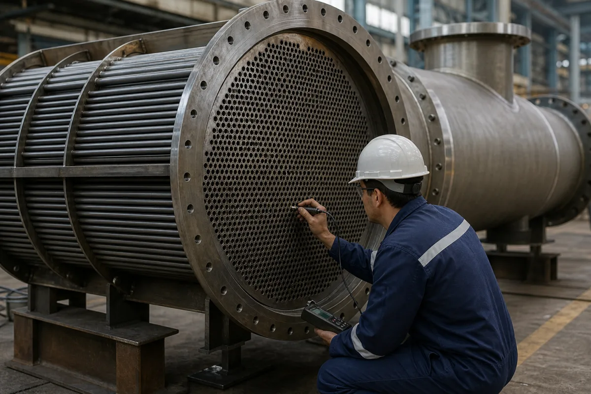
Process and vapour-recovery condensers · Surface (shell-and-tube, plate) versus contact condensers, TEMA front-head, shell and rear-head types, vertical and horizontal arrangements, recovery efficiency and coolant temperature, U and LMTD sizing, venting of non-condensables, icing and precoolers, outlet-temperature monitoring
A condenser is a heat exchanger that cools a vapour or gas stream until one or more components reach saturation and change to liquid, for product, solvent or raw-material recovery or to cut emissions; surface condensers (shell-and-tube or plate) keep the coolant separate, while contact condensers spray coolant into the gas. Ask three things first: which vapour, concentration and recovery the condenser must achieve, what coolant temperature that requires and whether water or freezing components will ice the surfaces, and what area, pressure drop, materials and refrigeration capacity the duty needs.
Process condensers and vapour-recovery condensers for chemical, solvent and fuel vapours: shell-and-tube and plate surface condensers, contact (direct-spray) condensers and packaged refrigerated condenser systems. General heat exchangers (see heat exchanger), vacuum cold traps (see cold trap condenser), steam turbine surface condensers, refrigeration-cycle condensers in chillers and air-cooled condensers for HVAC are outside this page except where compared.
CNFX editorial research · Sources checked October 12, 2026 · 6 sources
Chapter 2 of the US EPA Air Pollution Control Cost Manual (Refrigerated Condensers, RTI International and EPA, November 2017) explains that non-refrigerated condensers serve as raw material, product and solvent recovery devices in chemical process industries and ahead of other control devices, while refrigerated condensers treat streams with high VOC concentrations. Condensation happens when the partial pressure of the volatile compound equals its vapour pressure, so more volatile compounds need lower temperatures; a condenser cannot lower the outlet concentration below the saturation concentration at the coolant temperature. It gives removal efficiencies of about 50–90% with chilled water and brine, and above 90% with ammonia, liquid nitrogen, CFC, HCFC or HFC refrigerants, depending on the composition and concentration. [1]
Surface condensers keep the coolant out of contact with the vapour, so it can circulate in a closed loop and the condensate is recovered directly; shell-and-tube units circulate coolant in the tubes with the vapour condensing on the shell side, and plate-and-frame exchangers are also used. Contact condensers spray ambient or chilled liquid into the gas, so the spent coolant carries the VOC; the EPA states that spent coolant from contact condensers "can be a waste disposal problem." [1]
Design needs the gas flow, inlet temperature, VOC concentration and composition, required removal efficiency, moisture content and VOC properties (heat of condensation, heat capacity and vapour pressure, for example as Antoine constants). [1]
EPA's Air Emissions Monitoring Knowledge Base adds that condenser efficiencies vary from 50 to 95 percent depending on the gas stream and operating parameters such as coolant temperature, and that the stream's pollutants, moisture, particulate content, flow and temperature all affect performance. It names the condenser outlet VOC concentration and outlet gas temperature as the primary performance indicators, with coolant inlet and outlet temperature, gas flow, pressure differential across the condenser, coolant flow and condensate collection rate as further parameters; normal operation should include a maximum outlet gas temperature set point and fixed coolant inlet and outlet temperatures. [2]
Give the supplier the gas or vapour composition and flow, inlet temperature and pressure, VOC concentration, moisture content, required recovery or outlet concentration, coolant available (cooling water, chilled water, brine, refrigerant, liquid nitrogen) with supply temperature, allowable pressure drop, materials of construction, defrost method, condensate handling and storage, hazardous-area classification and installation constraints.
02
Size the area, control icing and set refrigeration
The manual sizes condensers from heat load, log-mean temperature difference (LMTD) and the overall heat-transfer coefficient U, with area A = H/(U·ΔTlm). For tubular exchangers condensing organic solvent vapours in non-condensible gas on the shell side with water or brine in the tubes, U ranges from 20 to 60 Btu/hr·ft²·°F; it uses 20 for a conservative, study-level (±30%) estimate and notes that fouling lowers U and raises the area. One ton of refrigeration is 12,000 Btu/hr; multistage systems are used below about −30 °F and cascade systems for −50 to −150 °F. [1]
The NPTEL chemical engineering design course (IITs and IISc) notes that a pure saturated vapour condenses almost isothermally, so the log-mean temperature difference can be used with no correction factor for multiple passes. For Kern's shell-side method it starts from an assumed condensing film coefficient of 100 to 300 BTU/h·ft²·°F for hydrocarbons, against 1500 BTU/h·ft²·°F for air-free steam. A condenser must have a vent to remove non-condensable gas, which lowers heat transfer; condensers use wider baffle spacing because the allowable shell-side vapour pressure drop is lower, with vertical-cut segmental baffles and an opening at the bottom for condensate drainage. For tube-side condensation it takes one-half of the conventional tube-side pressure-drop relation. Where desuperheating or subcooling is needed, a weighted mean temperature difference can be used if the sensible heat load is about 25% of the latent load; otherwise separate desuperheater and subcooler are more convenient. [3]
Editorial calculation: in the course's practice problem, n-propyl alcohol condenses at 244 °F against cooling water warming from 95 to 120 °F, so the end differences are 149 °F and 124 °F and LMTD = (149 − 124) / ln(149/124) ≈ 136 °F; the same 100,000 Btu/hr load used below would then need about 100,000 / (20 × 136) ≈ 37 ft² at the conservative EPA U of 20.
Where the gas holds water vapour or a VOC with a high freezing point such as benzene, ice or frozen hydrocarbons can form on tubes or plates, cutting heat transfer and removal efficiency and raising pressure drop. The manual describes a precooler that brings the stream to about 35–40 °F to remove moisture first, or an intermittent defrost by circulating ambient-temperature brine, radiant heating coils or, for intermittent systems, ambient air. Recovery tanks, pumps and blowers complete the system. [1]
Editorial calculation: a condenser with a heat load of 100,000 Btu/hr and an LMTD of 30 °F, sized with the conservative U of 20 Btu/hr·ft²·°F, needs about 100,000 / (20 × 30) ≈ 167 ft² (about 15.5 m²) of surface; the same load needs about 100,000 / 12,000 ≈ 8.3 tons of refrigeration if it is removed by a refrigerated coolant. [1]
03
Choose the shell-and-tube arrangement or a plate condenser
NPTEL describes vertical condensers, with vapour flowing down inside the tubes (condensate drains by gravity and vapour shear) or up inside them (gravity only), and horizontal condensers with condensation inside or outside the tubes. It notes that TEMA and IS 4503 give mechanical-design guidance for unfired shell-and-tube exchangers and that the TEMA three-letter code names the front end, shell and rear end. [3]
Its comparison: fixed-tubesheet units (TEMA BEM, AEM, NEN) provide the maximum heat transfer area for a given shell and tube diameter and are less costly than removable bundles, but the shell side cannot be cleaned mechanically and differential expansion needs a shell expansion joint; floating-head units (AEW, BEW, BEP, AEP, AES, BES) allow expansion and mechanical cleaning of both sides, at the cost of tube space lost to the bolt circle and packing limits on pressure and temperature; U-tube units (BEU, AEU) allow expansion and are less costly than floating heads, but the tubes can be cleaned only chemically and no single tube pass or true countercurrent flow is possible. [3]
TTE training notes on TEMA (8th edition, 1998) add that TEMA supplements pressure-vessel codes such as ASME and BS 5500; that the B bonnet front head suits clean tube-side duties and the A channel with removable cover dirty ones; that the E shell should be used if possible, with J or X shells where the allowable pressure drop cannot be met in an E shell; and that a fixed tubesheet suits a temperature difference below 50 °C, with shell bellows as special items limited to 35 bar. They suggest putting the dirty, high-pressure or special-material stream in the tubes. [4]
Plate condensers are the other surface type. Alfa Laval's AlfaCond 600 leaflet describes a semi-welded plate condenser for condensation under vacuum, with vapour in the welded channel and coolant in the gasketed channel; plates in 316/316L or titanium (allowing sea water as coolant), a free channel of 11 / 3 mm, a DN600 PN10 vapour inlet, DN150 condensate outlets and DN250 coolant connections, and a maximum design pressure of 6.0 barg on the vapour side and 10.0 barg on the cooling side at 160 °C under PED. [5]
In oilseed solvent extraction, Alfa Laval's solvent-recovery brochure describes hexane vapour passing through a primary condenser, a vent condenser and, in some cases, a safety condenser, with non-condensables going on to a mineral-oil vapour scrubbing system; it argues that very close temperature approaches minimise the non-condensable gases passed on to the scrubber, so each condenser can condense more solvent than a corresponding shell-and-tube unit. [6]
04
A graphite block-hole condenser maker
The one maker listed below, Nantong Tianwei, shows cylindrical block-hole graphite condensers on its website rather than the shell-and-tube or plate units described above.
05
Vent, precooler, refrigeration and the rest of a recovery package
Read the vent and precooler rows first if the gas carries non-condensables or water vapour.
Outlet gas temperature, coolant temperatures, pressure differential. [2]
Set points and records.
06
From recovery target to refrigeration tonnage, row by row
Recovery efficiency and overall U come from the EPA manual and drive the area; the pressure and temperature rating comes from one Alfa Laval plate condenser, not from a shell-and-tube unit.
Explore company information and manufacturing capabilities, then discuss the scope of your project with a relevant supplier.
Share this page
Compiled and source-reviewed by the CNFX editorial team.
Each manufacturer above links to the page on that company's own website where the product is listed, with the date we checked it. How we source and review
· Page last updated 13 October 2026
Buyer questions
How much vapour can a condenser recover?
EPA gives about 50–90% removal with chilled water or brine and above 90% with ammonia, liquid nitrogen or fluorinated refrigerants, depending on composition and concentration. [1]
What is the difference between surface and contact condensers?
Surface condensers keep the coolant separate so it can be recycled and the condensate recovered; contact condensers spray coolant into the gas, contaminating it. [1]
Why does a condenser ice up?
Water vapour or high-freezing VOCs such as benzene freeze on cold surfaces; a precooler to about 35–40 °F or a defrost cycle is used. [1]
Which shell-and-tube type suits a condenser?
NPTEL notes fixed-tubesheet types (BEM, AEM, NEN) provide maximum heat transfer area but no mechanical shell-side cleaning, while floating-head (AES, BES) and U-tube (BEU, AEU) types allow differential expansion. [3]
Sources and what still needs a direct check
Sources checked 2026-10-12. The EPA Control Cost Manual and monitoring guidance give study-level design, cost and monitoring information for condensers; the NPTEL course and TTE notes summarise TEMA types and design practice; the Alfa Laval figures come from the maker's own documents. Detailed thermal and mechanical design for your duty must come from the supplier and applicable pressure-equipment codes.