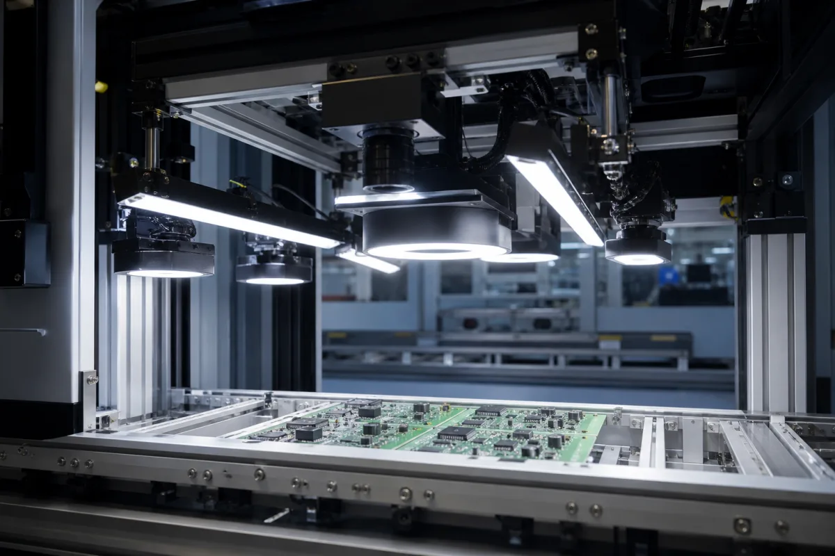
LED illumination system for solder-joint inspection: tiered red, green and blue ring lights that turn the slope of a solder fillet into colour
Tiered red, green and blue ring and dome lights for solder-joint AOI · lamps at 20°, 40° and 70° that pick out fillet slopes of 10°, 20° and 35°, switchable full-colour LED domes, 24 V lights of 27 to 52 W
Solder is shiny. Under a single light, a fillet shows a bright spot and dark areas that say little about its shape. AOI illumination for solder joints exploits that mirror-like surface: rings of red, green and blue LEDs sit around the camera axis at different angles, and each ring is reflected into the camera only by the parts of the fillet tilted at the matching slope. The image becomes a colour map of fillet slope that software compares with a good joint. Choosing such a system means choosing the angles, the colours and their order, the diameter that suits the field of view, and whether the angles are fixed or switchable.
Multi-angle, multi-colour LED illumination for automated optical inspection of solder joints and component mounting on printed circuit boards: tiered RGB ring lights, RGB dome lights and switchable full-colour LED illuminators, with their angles, colours, diameters and power. Complete AOI machines with their cameras, resolution and software are covered on the Automated optical inspection (AOI) system for PCB assembly page; general machine vision ring, bar, dome and back lights with strobe controllers on the LED lighting system for machine vision page; vision computers that drive lights from built-in outputs on the Image processing unit page; LED modules for general and industrial luminaires on the LED light module page; reflectors for luminaires on the Precision reflector assembly page; luminaire assembly and test lines on their own page.
CNFX editorial research · Sources checked October 12, 2026 · 4 sources
Blue at 20°, red at 40°, green at 70°: how three rings map fillet slopes of 10°, 20° and 35°
Samsung Electronics' solder-joint inspection patent gives a complete tiered geometry. Green, red and blue circular lamps are stacked coaxially around a colour camera, decreasing in diameter and increasing in height above the board: green about 130 mm across, red about 70 mm and blue about 40 mm, set so that their light reaches the inspection area at about 70°, 40° and 20° from the camera axis. In its example the inclined solder surfaces those rings pick out have slopes of about 35°, 20° and 10°. [1]
The patent explains the mechanism: when the lamp diameter is larger than the surface patch, each ring acts as a set of point sources at one polar angle, and a specular surface returns a highlight to the camera only where the surface normal bisects the angle between the light source and the camera. Shiny leads and solder therefore show distinct red, green and blue patterns according to their tilt, while rough surfaces such as a plastic component body do not. [1]
Editorial calculation: for a camera looking straight down, the bisector condition gives surface slope = incidence angle / 2, so 20° / 2 = 10°, 40° / 2 = 20° and 70° / 2 = 35°, which reproduces the three slopes in the patent. A fillet steeper than 35° would need light from beyond 70°, close to grazing incidence. [1]
The lamps in that patent are high-frequency neon rings; its camera has a 1:7 zoom covering fields from 4 × 3 mm to 28 × 21 mm, and its inspection field is set at 12 × 9 mm, holding five or six joints. [1] The same tiered RGB principle is now built with LEDs, as the following sections show.
Ask the supplier for the incidence angle and colour of each ring measured from the camera axis at the working distance, so you can check which fillet slopes each colour will show.
02
When fixed tiers miss steep fillets: full-colour LED domes switched in five angular sections
Omron's patent application describes the limitation of its own earlier three-ring illuminator: because the angular range of each colour is fixed, the relationship between colour and slope is fixed too, and if a solder fillet becomes very steep it becomes difficult to display a colour distribution that reflects the change in slope, so the slope may not be detected. [2]
Its answer replaces the three rings with an array of full-colour LED lamps, each containing red, green and blue emitters, mounted on boards around the camera's optical axis. The angular range over which light can reach the inspection area is divided into five sections, A to E in increasing angle of elevation, and the lamps are switched on and off section by section, so the colour and angle of illumination can be changed according to the kind and purpose of the inspection with the same hardware. [2]
An earlier Hughes Aircraft patent on recovering solder shape from shading shows why two fixed angles are not enough across a wide slope range. With two lights tilted 35° and 70° from the vertical, a pixel of intensity 100 under the 35° light could belong to a surface tilted either 11° or 26°; the 70° light separates them, giving intensities near 0 and near 80 respectively. Even so, the inventors state that the two-light arrangement cannot accurately recover tilts below 10° or above 55° when the swing is non-zero, because one of the two images is dark there. [3]
If your boards carry joints with very steep or very flat fillets, ask whether the illuminator can change the angle and colour assignment per inspection item, and how many independently switched angular zones it has.
03
RGB AOI ring lights from 27 W to 52 W at 24 V: diameters, coaxial-plus-ring versions and controllers
OPT's AOI light series shows what a commercial tiered RGB illuminator looks like. The RIA lights are aluminium-shelled LED rings with a heat transfer layer, circuit board and diffuser, described as using special diffusers for uniformity and multi-colour illumination from different angles to bring out 3D information on solder. [4]
All four are listed with the OPT-DPA1024E controller, 800 mm leads and JST SMR-02V-B connectors; the brochure lists customisation by colour, size, installation method, multi-angle light combination and independent control of different areas. [4] Editorial calculation: at 24 V, 27.1 W is about 1.13 A and 52.1 W about 2.17 A for the whole light. [4]
Smaller RGB lights in the same catalogue show the power scale for single-colour channels: the OPT-RI 6215-RGB 3C ring is rated 0.5 W, 0.9 W and 1.1 W per colour at 24 V, and the OPT-RID240-RGB dome 7.2 W, 14.4 W and 14.4 W. [4]
Match the inner opening to the camera's field of view and working distance, and ask for the angle of each colour band from the drawing, the controller channel count, and whether each colour can be dimmed separately.
04
Board, joint and optics data for an AOI illumination system
Paste it into your enquiry below or into an email to a maker, then replace every bracket.
Boards: [size; component types; lead-free or leaded solder]
Joints to judge: [chip fillets; gull-wing leads; through-hole; expected slope range]
Camera: [field of view; working distance; lens; colour or mono]
Illumination: [ring or dome; colours; angle of each band; RGB plus white or coaxial]
Switching: [fixed tiers or zones; number of independent zones]
Power: [24 V; watts per light; controller channels]
Mechanics: [outer and inner diameter; mounting; cable and connector]
Explore company information and manufacturing capabilities, then discuss the scope of your project with a relevant supplier.
Share this page
Compiled and source-reviewed by the CNFX editorial team.
Each manufacturer above links to the page on that company's own website where the product is listed, with the date we checked it. How we source and review
· Page last updated 13 October 2026
Buyer questions
Why do AOI lights use red, green and blue rings?
Each colour ring sits at a different angle, and a shiny solder surface reflects a ring into the camera only where its tilt matches; the colours therefore map fillet slope. In Samsung's patent, rings at 20°, 40° and 70° pick out slopes of about 10°, 20° and 35°. [1]
What is the limitation of fixed three-colour rings?
Omron notes that the colour-to-slope relation is fixed, so very steep fillets may show no colour change; its design uses full-colour LEDs switched in five angular sections. [2]
How much power does an RGB AOI ring light draw?
OPT lists its RIA200, RIA211 and RIA250 RGB AOI lights at 27.1 W, 32.0 W and 52.1 W at 24 V. [4]
Sources and what still needs a direct check
Sources checked 2026-10-12. Geometry and principles come from patents by Samsung Electronics, Omron and Hughes Aircraft; product ratings come from OPT's AOI light brochure as distributed by Maxxvision.