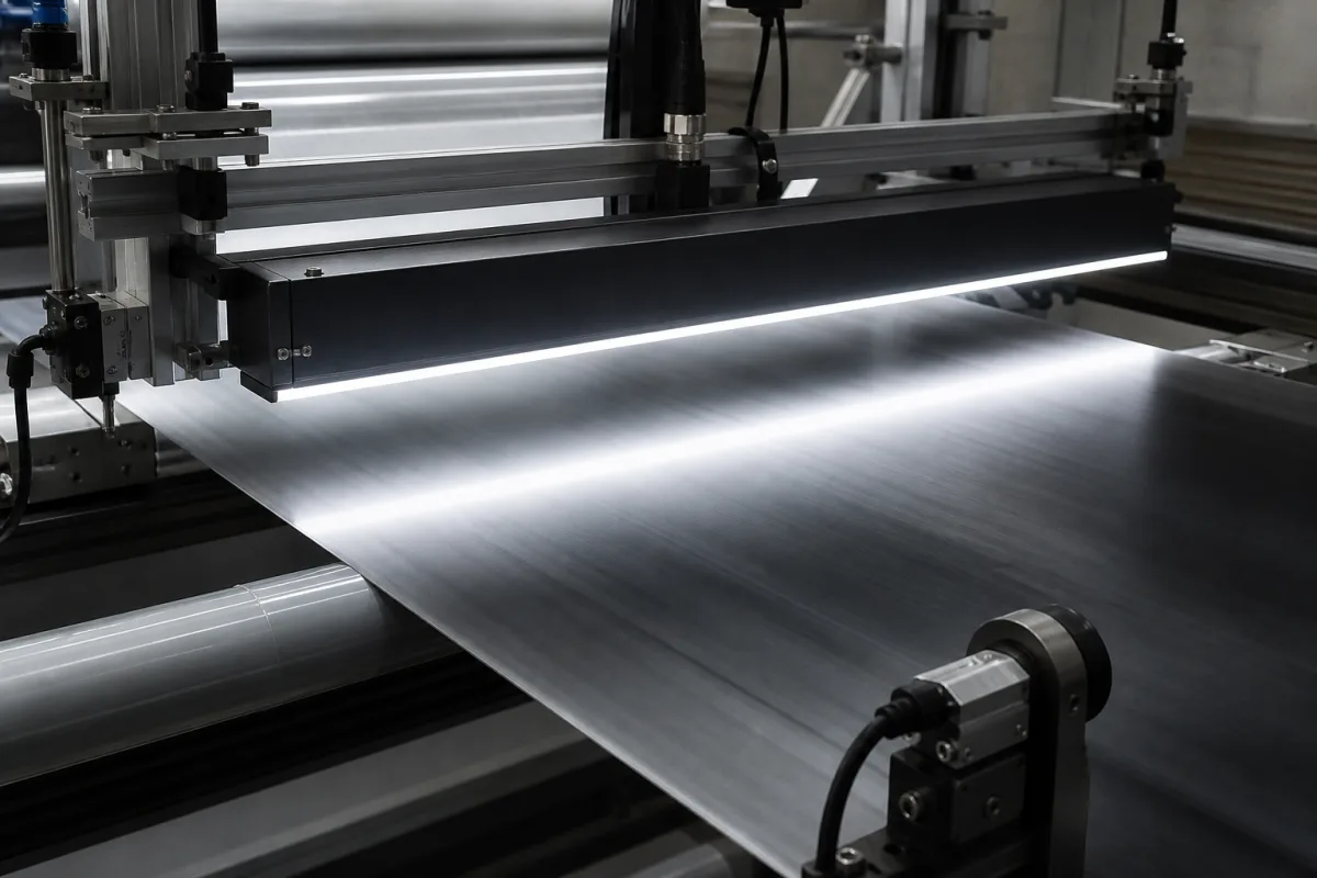
Machine vision for moving webs · Pixel count, line rate and encoder sync, colour line sensors, TDI
A line scan camera captures one row of pixels at a time and builds an image by stacking lines as the object moves past, so it suits continuous webs such as film, foil, paper, textiles and battery electrodes, and objects on conveyors or rollers. Ask three things first: how many pixels the line needs across your field of view, what line rate your object speed demands and how the camera will be synchronised to the motion, and whether you need colour, NIR or TDI sensitivity.
Industrial line scan cameras, monochrome, colour and TDI, for machine vision. Area scan cameras, line scan lenses and lighting, frame grabbers and complete inspection systems are outside this page.
CNFX editorial research · Sources checked October 11, 2026 · 5 sources
Edmund Optics' line scan white paper calculates the minimum array as horizontal field of view × pixels per feature ÷ feature size, and the required line rate as object speed ÷ object-space pixel size. Its OCR example, with a 100 mm field of view, 0.5 mm features, 10 pixels per feature and 500 mm/s, needs 2,000 pixels and a 0.05 mm object pixel, so 500 ÷ 0.05 = 10,000 lines per second (10 kHz). [1]
The paper gives line-sensor lengths of 2k (2,048), 4k (4,096), 8k (8,192) or 16k (16,384) pixels; a 4k sensor with 7 µm pixels is 28.7 mm long, and behind a 50 mm lens at 250 mm working distance (0.2×) each pixel sees a 35 µm slice of the object. [1]
Editorial calculation with Edmund's formulas: a 1,200 mm wide web inspected at a 0.1 mm object pixel needs 12,000 pixels, so a 16k camera; at 60 m/min (1,000 mm/s) the line rate is 1,000 ÷ 0.1 = 10 kHz, and the 16,384-pixel line then produces about 164 million pixels per second for the interface and processing to carry. [1]
Give the supplier the object or web width and speed range, smallest defect and pixels per defect, required object pixel size, working distance, colour or NIR needs, lighting type, the encoder or trigger signal available, interface and frame grabber, cable length, ambient temperature and mounting.
02
Synchronise line capture to the motion
Edmund Optics explains that manual matching of line rate to object speed is difficult because lines are microns wide and rates are in kilohertz; if the object moves too slowly for the line rate the image is over-triggered and elongated, and if it moves too fast it is under-triggered and compressed. The paper describes synchronisation with an encoder on the motion source wired to a camera I/O port, with a multiply/divide ratio in the SDK matching encoder resolution to the object pixel size. [1]
Teledyne explains that time delay and integration (TDI) sensors accumulate multiple exposures of the same moving object, raising effective integration time so that the web can run faster or with less light, and averaging out light fluctuations so that AC or LED lighting can be used. Teledyne says that "in most applications, a TDI device can comfortably tolerate a 2-4% velocity mismatch", which a web-mounted encoder supplying the sync signal achieves even when the web changes speed; a total misalignment of one pixel or less across the sensor does not affect image quality. [2]
Editorial note: ask the supplier for the maximum line rate in the exact mode you will use (TDI stages, bit depth, region of interest), because these settings and the interface can lower it.
03
Choose monochrome, colour or multispectral sensors
Edmund Optics explains that a Bayer pattern cannot be applied to a single line, so colour line scan uses other layouts: bi-linear sensors (a green line plus an alternating red/blue line) still need interpolation, tri-linear sensors add a third line so each pixel gets true red, green and blue, multispectral sensors add a fourth NIR line, and prism cameras split light onto three sensors, giving true colour but needing special lenses. It describes each subsequent technique as "generally representing a more expensive solution". [1]
Editorial note: tri-linear and multispectral sensors capture the colour lines at slightly different moments, so they depend even more on good encoder synchronisation.
04
Compare what suppliers offer
Suppliers linked to this page list line scan cameras; each card links to the page reviewed.
The supplier reviewed lists line scan, TDI and SWIR line scan cameras with area scan cameras; ask for line rate per mode, pixel size, sensor type, interface and encoder input specification.
05
Read the data sheet's test conditions, power and environment limits
A maker's specification page shows which conditions a headline line rate depends on. Basler's documentation for its r2L16384-60cc colour line scan camera lists 16,384 × 1 pixels of 3.5 × 3.5 µm on a 57.34 mm sensor with two lines (green in one, red and blue alternating in the other), a CoaXPress 2× CXP-12 interface and 10-bit sensor depth. [3] Its 60 kHz line rate is stated as measured with two CXP cables, an 8-bit pixel format and minimum exposure time, and the same 60 kHz is listed for free run and for each hardware-trigger mode, including line-start triggers on I/O lines 1, 2 or 3. [3] Ask any supplier for the line rate under your own pixel format, exposure and trigger mode.
The same page sets the installation envelope: power over CoaXPress at 24 VDC or 18.6–26 VDC through the I/O connector, about 9 W at 24 VDC, an M72x0.75 lens mount, 420 g, IP30, and a housing temperature of 0–50 °C in operation with 80 % relative humidity non-condensing as the upper limit. [3] Basler adds that its racer 2 L colour cameras ship without an IR cut filter, and recommends one with 400–650 nm transmission and 650–1100 nm blocking when the light source emits significant infrared. [3]
Editorial calculation: 16,384 pixels × 60,000 lines per second ≈ 983 million pixels per second, which the frame grabber and both CXP-12 links must carry; 16,384 × 3.5 µm ≈ 57.3 mm, matching the stated sensor format and setting the lens image circle. [3]
06
Compare two 4K GigE line scan cameras: monochrome and trilinear colour
JAI's specification pages for two 4K (4,096-pixel) Sweep series cameras show how pixel size, sensor length and interface move together. The monochrome SW-4005M-5GE has 3.5 × 3.5 µm pixels on a 14.336 mm sensor, a C-mount, a 5GBASE-T interface and up to 84 kHz (84,000 lines/s), with 8, 10 and 12-bit output and 0 °C to +45 °C ambient operation. [4] The trilinear colour SW-4000TL-10GE has 7.5 × 7.5 µm pixels on a 30.72 mm sensor, an F-mount or M42 mount, a 10 GBASE-T interface that falls back to NBASE-T and 1000BASE-T, up to 66 kHz, 9.3 W power consumption and −5 °C to +45 °C ambient operation. [5]
Both pages list direct connection to rotary encoders: the SW-4005M-5GE adds resume scanning via a backward counter and a trigger delay based on trigger counts, and the SW-4000TL-10GE adds automatic scan-direction detection for reciprocating slide tables and daisy-chaining of encoder signals between cameras. The colour model also lists vertical dual-line binning, 2× horizontal binning and built-in conversion from RGB to HSI, CIE XYZ, sRGB and Adobe RGB. [4][5]
Editorial calculation: with Edmund Optics' 0.05 mm object pixel, [1] 84 kHz supports 84,000 × 0.05 mm = 4.2 m/s and 66 kHz supports 3.3 m/s. At 8 bits per pixel the monochrome camera's 4,096 × 84,000 lines/s is about 2.75 Gbit/s, inside a 5 Gbit/s link, and the colour camera's 4,096 × 3 channels × 66,000 lines/s is about 6.49 Gbit/s, inside 10 Gbit/s; protocol overhead is not included. The colour camera's larger pixels also double the sensor length, so a lens covering 30.72 mm is needed instead of a C-mount lens covering 14.3 mm. [4][5]
Fill the specification fields with values for your line
A line scan camera quotation needs values for your object and line. The table explains each field, gives published values where a reviewed source states them, and says what to obtain from the supplier.
Field
What it means and published values
Ask the supplier for
Resolution (pixels)
FOV × pixels per feature ÷ feature size; 2k–16k in standard use. [1]
Explore company information and manufacturing capabilities, then discuss the scope of your project with a relevant supplier.
Share this page
Compiled and source-reviewed by the CNFX editorial team.
Published product pages show what a company offers, not tested performance. Confirm the legal seller, factory and scope for your order. How we source and review
· Page last updated 13 October 2026
Buyer questions
How do I calculate the line rate for a line scan camera?
Divide object speed by the object-space pixel size; Edmund's example of 500 mm/s and 0.05 mm gives 10 kHz. [1]
Why use an encoder with a line scan camera?
Without synchronisation the image is elongated or compressed when speed and line rate differ; an encoder triggers lines from the motion itself. [1]
What does TDI add to a line scan camera?
It accumulates multiple exposures of the moving object for more sensitivity, tolerating about a 2–4% speed mismatch with encoder sync. [2]
Does a line scan camera reach its rated line rate in every mode?
Check the conditions printed with the figure: Basler states the 60 kHz of its r2L16384-60cc as measured with two CXP cables, an 8-bit pixel format and minimum exposure time. [3]
How fast can a 4K GigE line scan camera run?
JAI lists 84 kHz for its 3.5 µm monochrome SW-4005M-5GE on 5GBASE-T and 66 kHz for its 7.5 µm trilinear colour SW-4000TL-10GE on 10 GBASE-T. [4][5]
Sources and what still needs a direct check
Sources checked 2026-10-11. Edmund Optics and Teledyne are machine-vision suppliers explaining line scan and TDI design, and Basler's and JAI's specification pages show how makers state line rate, pixel size and interface; camera figures for your line must come from the chosen camera's data sheet.