Isolated voltage sensors · Primary current and loss, accuracy over temperature, bandwidth and delay, insulation test voltage, output and burden
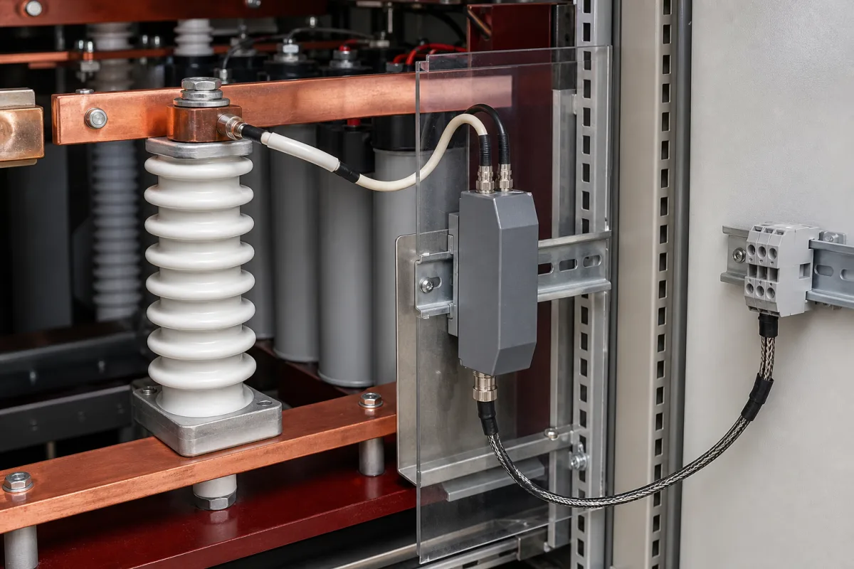
An isolated voltage sensor (voltage transducer) measures a DC, AC or pulsed voltage on a power circuit and delivers a proportional signal on a galvanically separated secondary circuit, for converters, drives, battery systems, chargers and switchgear; the panel-mounted sensor pictured takes its primary connection from a busbar. Ask three things first: how much current and power the sensor draws from the circuit it measures, what its total error is across your temperature range and how fast it responds, and what insulation it has between primary and secondary for your voltage and installation category.
Galvanically isolated voltage sensors and transducers for DC, AC and pulsed voltages in power electronics, battery systems and panels. Voltage transformers for metering, capacitive voltage indicators, panel meters and multimeters are outside this page.
CNFX editorial research · Sources checked October 12, 2026 · 4 sources
Check what the sensor draws and how accurate it stays
LEM's LV 25-1000, a closed-loop Hall effect voltage transducer with its primary resistor on the circuit board, takes a primary current of 8 mA at its 1000 V nominal voltage (measuring range ±1500 V), giving a total primary power loss of 8 W. Its total error at nominal voltage and 25 °C is ±0.8%, linearity better than 0.2%, offset ±0.15 mA with up to ±0.60 mA added over −25 to 25 °C, and it operates from −25 to 70 °C. [1]
LEM's DVL 1000, for the same 1000 V nominal and ±1500 V range, has a primary resistance of 11.3 MΩ and total primary power loss of 0.09 mW. Its total error is ±0.5% of nominal at 25 °C and ±1% over −40 to 85 °C, its sensitivity error ±0.2% and linearity error ±0.5% of the measuring range, and it operates from −40 to 85 °C. [2]
Editorial calculation: at a 1000 V nominal, ±1% total error over temperature is ±10 V, which matters if the reading feeds a battery cut-off or protection threshold; the 8 W drawn by a resistor-input sensor at full voltage must also be dissipated on its board.
Give the supplier the nominal and maximum voltage, whether DC, AC or pulsed, required accuracy over the operating temperature range, bandwidth or response time, output type and burden, supply voltage, insulation requirements (system voltage, overvoltage category, pollution degree), mounting and connections, and the standards the equipment must meet.
02
Check response, insulation and output burden
The LV 25-1000 is rated for a delay under 40 µs to 90% of output for a nominal voltage step (at 50 V/µs) and an AC insulation test of 4.1 kV RMS for 1 minute between primary and secondary, with 13.8 mm creepage and clearance and a CTI below 175; LEM's application example under EN 50178 and IEC 61010-1 assumes overvoltage category 3, pollution degree 2, and use in limited-energy secondary circuits. [1]
The DVL 1000 lists a −3 dB bandwidth of 14 kHz, a 90% delay of 50 to 60 µs for a 0 to 1000 V step at 6 kV/µs, an AC insulation test of 8.5 kV RMS for 1 minute (100% tested in production), 16 kV impulse withstand, partial discharge test at 2,700 V, insulation resistance of 200 MΩ at 500 V DC, CTI 600 and railway standards including EN 50155 and EN 50124-1. [2]
Both sensors have a current output that must be turned into a voltage through a measuring resistor within limits. The LV 25-1000 gives 25 mA at nominal voltage and needs a measuring resistance of 100 to 320 Ω at ±15 V supply for ±1000 V; the DVL 1000 gives 50 mA (50 µA/V) and allows up to 133 Ω. Editorial calculation: across a 100 Ω resistor these give about 2.5 V and 5 V at 1000 V. [1][2]
A Chinese maker's range shows the two input styles side by side. Cheemi Technology's Hall voltage sensor table lists the CHV_LV15D50L, rated directly in volts for nominal voltages from 100 V to 5,000 V, ±50 mA output, a 0–7,500 V measuring range, ±15 to ±24 V supply, 0.5% accuracy at 25 °C and M5 stud mounting; and current-input PCB sensors such as the CHV_AS5S6, which take a 5 or 10 mA nominal primary current (0 to ±20 mA range) through the user's own series resistor and give 2.5 ± 0.625 V output from a single +5 V supply. [3]
Editorial calculation: for a current-input sensor at 10 mA nominal on a 1,000 V bus, the user's series resistor must be about 1,000 V ÷ 0.010 A = 100 kΩ and dissipates about 10 W at nominal voltage, so its rating, voltage withstand and temperature drift set much of the accuracy; a sensor rated directly in volts, like the 0–7,500 V model, leaves that design to the maker. [3]
03
Compare what suppliers offer
Suppliers linked to this page list voltage sensors; each card links to the page reviewed.
Listings include Hall effect voltage sensors for photovoltaic, electric vehicle and railway use, closed-loop current and voltage sensor ranges, combined current and voltage sensors, and high-voltage sensors for switchgear. Ask each supplier for the full datasheet with total error over temperature, primary power draw, bandwidth and the insulation test voltage.
Some equipment builders put the isolation on their own board instead of buying a transducer module. Texas Instruments' AMC1311 is an isolated amplifier with a 2 V high-impedance input meant to sit behind a resistive divider; TI lists a capacitive isolation barrier with 5,000 V RMS withstand for 1 minute per UL1577, 7,000 V peak transient isolation under DIN EN IEC 60747-17 (VDE 0884-17), 1,500 V RMS working voltage, 8.5 mm minimum creepage and clearance, and an 8-pin SOIC package. For the AMC1311B grade TI lists ±0.2% maximum gain error, ±40 ppm/°C maximum gain drift, ±1.5 mV maximum offset, 0.04% maximum nonlinearity and 100 kV/µs minimum CMTI, with the AMC1311B specified from −55 to 125 °C. [4]
Editorial calculation: to bring a 1,000 V bus down to the AMC1311's 2 V input the divider needs a 500:1 ratio, and the divider resistors then carry the high-voltage stress and much of the drift budget, the same trade-off as the user's series resistor on a current-input transducer. [4]
04
Trace the sensor parts
This is a functional reference built from the sources cited; it is not one maker's specification.
Part
Role
Fix in the order
Primary input
Takes a small current from the measured voltage; built-in or user resistor. [1][2][3]
Fill the specification fields with values for your circuit
A voltage sensor quotation needs values for your circuit. The table explains each field, gives published values where a reviewed source states them, and says what to obtain from the supplier.
Field
What it means and published values
Ask the supplier for
Measurement Range (V DC)
Examples: 1000 V nominal, ±1500 V range; 100–5,000 V nominal, 0–7,500 V range. [1][2][3]
Nominal and range.
Accuracy (% FS)
Example: ±0.5% at 25 °C, ±1% over temperature. [2]
Explore company information and manufacturing capabilities, then discuss the scope of your project with a relevant supplier.
Share this page
Compiled and source-reviewed by the CNFX editorial team.
Published product pages show what a company offers, not tested performance. Confirm the legal seller, factory and scope for your order. How we source and review
· Page last updated 13 October 2026
Buyer questions
How much power does a voltage transducer draw from the circuit?
It depends on the design: LEM's LV 25-1000 draws 8 mA at 1000 V, an 8 W loss, while its DVL 1000 draws 0.09 mW. [1][2]
How accurate is an isolated voltage sensor over temperature?
LEM's DVL 1000 lists ±0.5% total error at 25 °C and ±1% over −40 to 85 °C. [2]
What insulation test voltage should I look for?
It depends on your system; LEM lists 4.1 kV RMS for the LV 25-1000 and 8.5 kV RMS for the DVL 1000, each for 1 minute. [1][2]
What is the difference between a current-input and a voltage-input voltage sensor?
A current-input sensor takes a few mA through your own series resistor (about 100 kΩ for 10 mA at 1,000 V); a model rated directly in volts, such as one rated 100–5,000 V, takes the bus voltage itself. [3]
Can I sense high voltage with an isolated amplifier IC instead of a transducer module?
Yes, with your own resistive divider: Texas Instruments' AMC1311 takes a 2 V input and lists 5,000 V RMS withstand for 1 minute, 1,500 V RMS working voltage and ±0.2% maximum gain error for the B grade; a 1,000 V bus needs a 500:1 divider (editorial calculation). [4]
Sources and what still needs a direct check
Sources checked 2026-10-12. LEM is a maker of current and voltage transducers; the datasheets give its values for two models. Texas Instruments' AMC1311 product page gives the values for a board-level isolated amplifier used with a resistive divider, and a Chinese maker's product table shows a third range.