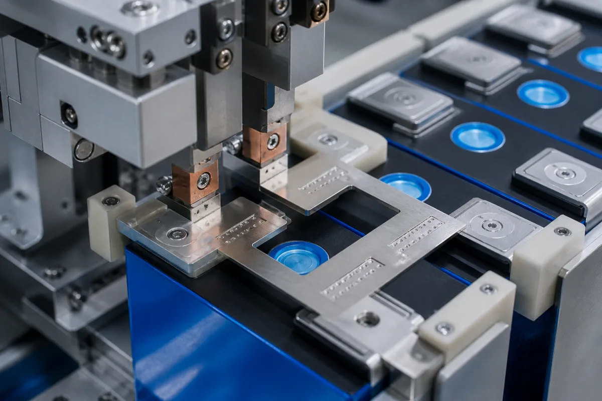
Cell-terminal interconnects: material stack, qualified joining and defined electrical test path
A battery cell interconnect joins cell tabs or terminals to a busbar or connector plate within a module. Determine the current through each connection from the actual series/parallel layout and current path; not every connection necessarily carries the same cell or module current.
Busbars and interconnect plates joined to the tabs or terminals of lithium-ion cells in modules and packs, with their materials, plating and joining by laser, ultrasonic or resistance welding. Cell manufacturing (electrode foil to tab welding inside the cell), general power busbars (see copper busbar) and battery management systems are outside this page except where compared.
CNFX editorial research · Sources checked October 18, 2026 · 4 sources
Qualify the material stack and joining process together
The Micromachines review compares resistance, laser and ultrasonic welding through heat input, metallurgy, electrical resistance, mechanical robustness and production constraints. It identifies trade-offs rather than one universally superior process. The actual tab/busbar materials, thickness, plating, access and tooling therefore belong with the weld qualification. [2]
The Warwick study tested 0.3 mm Al, Cu, nickel-plated Cu and Ni tabs joined to 1.5 mm Al or Cu busbars using its laser arrangement. Its mechanical, resistance and temperature results belong to those specimens and selected welding conditions; they are not the supplied connector’s current rating, strength or guaranteed weight/cost saving. [1]
The separate ultrasonic study used 0.5 mm AA1100 aluminium and 0.3 mm CuNi UNS C71500. CuNi alloy sheet is not the same stack as nickel-plated copper. It reports a maximum lap-shear load of 942 N at 1,200 J, 0.24 MPa sonotrode pressure and 68 µm amplitude, followed by lower strength at higher energy in that series. This laboratory process point is not a universal weld setting for battery connectors. [3]
02
Retain current, elapsed time and measurement geometry with resistance
Warwick reports that Cu-tab/Cu-busbar specimen resistance rose during the test. At the end of 180 s, its reported values were approximately 0.044 mΩ at 100 A, 0.048 mΩ at 150 A and 0.050 mΩ at 200 A. These are current- and time-dependent results from the specified test arrangement, not a generic connector resistance range or a continuous-current qualification. [1]
Editorial calculation: assuming a single measured path has constant resistance of 0.050 mΩ while carrying steady 200 A, with temperature dependence ignored for this calculation, I²R = 200² × 0.000050 = 2.0 W. This is an ideal calculation using the study’s stated inputs, not manufacturer-published performance of a supplied connector and not an independent measured module heat load. Do not multiply it by an unspecified number of connections without their actual currents and resistances. [1]
The ultrasonic paper’s Methods says resistance was measured with 200 A for 90 s, while its resistance/temperature Results describes 200 A for 60 s. Both durations are in the source. Confirm the exposure time and associated data with the authors before using those results as an acceptance benchmark. [3]
03
Keep the green-laser study’s measurement stages separate
Kaufmann and colleagues studied nickel-coated Cu over Al using green-laser overlap welding. Their electrical resistance measurements and reference conductors belong to that specimen geometry and measurement path. The reported 42.2 µΩ minimum for the identified stitched parameter set cannot be ranked directly against Warwick’s Cu–Cu result as though the materials, probe positions, test current and thermal state were identical. [4][1]
The green-laser paper describes thermocouples 20 mm from the weld symmetry plane in its initial setup and, in the later in-situ setup, temperature sensors 8 mm from the symmetry plane with a 16 mm electrical test length. These describe different investigation stages; do not attach the later sensor position to every earlier temperature result. [4]
Its cited 65°C criterion concerns a seam-adjacent, cell-internal-tab context from earlier literature. It is not a universal cell-connector operating-temperature rating or an allowed weld-interface temperature for every cell construction. Obtain limits and measurement locations approved for the actual cell and assembly. [4]
04
Check the conductor, weld, support and insulation as one assembly
The review distinguishes cell tabs from the busbars joining them. Identify the terminal/plating, connector geometry, joint pattern, support and insulation, including the actual branch currents. The illustration shows a connector plate at prismatic-cell terminals; it does not establish material grade, weld process parameters or an accepted joint. [2]
Use the actual connection drawing and part stack to define mechanical, electrical and thermal tests. Coupon strength alone does not establish vibration/thermal-cycle life of the supported module, and a low measured path resistance alone does not qualify the weld metallurgy. [1][4]
05
Define the supplier’s acceptance evidence for the actual module
Specify the cell/terminal materials and plating, connector drawing, series/parallel current paths, current profile, joining access and process window. Require the resistance method and probe locations, applied current and duration, temperature measurement location, mechanical test mode and inspection plan. [2][1]
Keep each laboratory study’s material stack and test conditions with its result. Resolve source inconsistencies with the authors and qualify the supplied assembly against the cell manufacturer’s constraints; do not turn cross-study calculations into measured operating performance. [3][4]
06
Send the cell, current and joint data together
Paste it into your enquiry below or into an email to a maker, then replace every bracket.
1 company lists this product among what they make. Company figures are quoted from each
company's own website; every card states where the relationship came from.
Xiamen Apollo Stamping Welding Technology Co., Ltd
TBC
Official product page offers nickel-plated copper battery busbars with PVC insulation and custom geometry. Confirm the actual terminal interface, insulation clearance and qualified joining arrangement.
Explore company information and manufacturing capabilities, then discuss the scope of your project with a relevant supplier.
Share this page
Compiled and source-reviewed by the CNFX editorial team.
Each manufacturer above links to the page on that company's own website where the product is listed, with the date we checked it. How we source and review
· Page last updated 13 October 2026
Buyer questions
Do the reported laboratory resistance values rate every connector for that current?
Warwick’s values depend on its material stack, measurement path, applied current and elapsed time. Qualify the actual connector and module conditions separately. [1]
Does the ultrasonic paper state one consistent electrical-test duration?
Its Methods says 90 s and its resistance/temperature Results says 60 s, both at 200 A. Confirm the associated data and duration with the authors. [3]
Can the green-laser result be compared directly with the Warwick Cu–Cu result?
The studies use different materials and measurement arrangements. Align material stacks, probe geometry, current and thermal conditions before ranking a supplied connector. [4][1]
Sources and evidence scope
Sources checked 2026-10-18. A welding-method review and three laboratory studies with different material stacks, test geometry and current/time conditions. Their results are research evidence, not current ratings or acceptance guarantees for a supplied connector.