Power-inverter interfaces — compatible controls and interpretable indications
An inverter panel needs a defined relationship with the inverter it serves: which readings it receives, what its indicators mean and which commands it can issue. Establish that compatibility before selecting the screen, bezel or remote cable.
Local or wired remote display/indicator interfaces for DC-to-AC power inverters. This guide covers the panel and its supported monitoring/control interface. Complete inverter power-stage sizing is covered by the power-inverter guide; generic panel PCs, motor-drive operator panels and independent battery monitors are separate products.
Order the panel as an identified inverter accessory or interface assembly
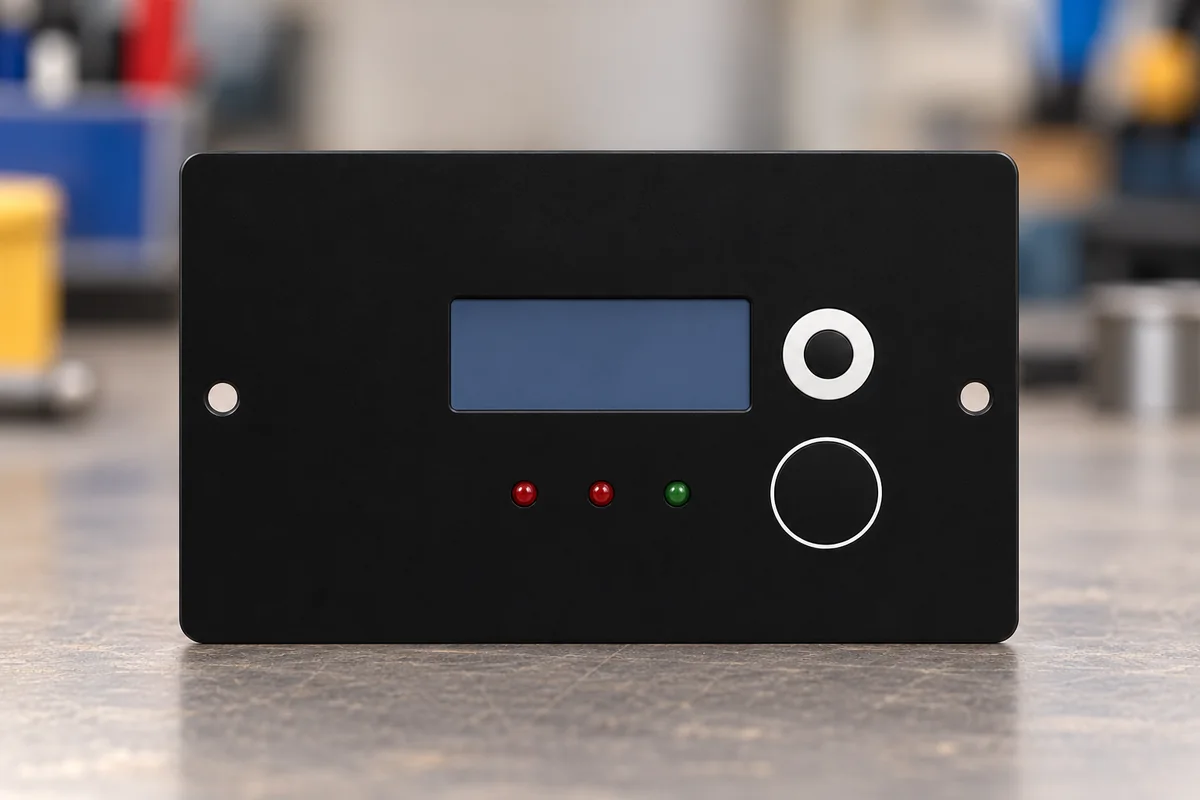
Samlex’s RC-300 specification identifies compatible PST inverter models and lists an LCD plus separate status LEDs. Victron’s REC040010210R manual describes an on/off panel for VE.Direct inverter models. These examples offer different user functions; specify the panel and inverter pairing explicitly. [2][3]
Record the inverter model and revision, the approved panel part number, available commands and any prerequisite local-switch setting. Identify whether the order is a complete remote panel, a replacement front assembly or a display module intended for integration into a controller.
The RC-300 uses a rolled-over RJ-50 cable. Its manual defines the signals at both ends; match that cable and pin assignment to the supported inverter. [1]
Victron’s panel diagram connects the control to the inverter’s H/L remote terminals, with polarity indicated. The product name includes VE.Direct, but that diagram identifies a remote-control connection. Confirm the actual electrical function instead of inferring a data interface from a name or connector appearance. [3]
For a custom panel assembly, obtain the controller-board interface definition: power source and limits, communications or discrete signals, command handling, unavailable-data behavior and the supported firmware. Define any separate supply and the panel’s operating and sleep consumption with the supplied backlight and indicators.
02
Define what a displayed value or indicator actually tells the operator
The RC-300 specification lists AC voltage, current, frequency, active power, apparent power and power factor. Establish the required quantity list and units for the offered panel; add battery or DC-input information only where the matched system supplies it. [2]
The RC-300 manual describes zero readings during its 2–6 second initialization. Below 6 W AC output, current, active/apparent power and power factor are shown as zero. Those display rules belong to this model. [1]
Its LCD sleeps after 3 minutes from the display-button press and can be awakened with that button. A sleeping LCD and an inverter shutdown are distinct states. [1]
The same manual defines the green POWER indication around the operating input section; the overload and over-temperature LEDs indicate corresponding AC-output shutdowns. Verify the indicated state against the inverter manual. [1]
Demonstrate supported controls with the matched inverter under an agreed test plan. Observe the local switch, panel command and resulting status together. Record which commands are available, any access restriction and the behavior after a communication interruption or restart.
Panel state
Meaning to verify in the demonstration
Startup
Time until readings are valid and the indication shown before data is available.
Low or absent load
Which quantities are suppressed, rounded or represented as zero.
Screen sleep
Which indications remain active and the action needed to wake the screen.
Alarm or shutdown
The detected condition, affected inverter function and operator response in the applicable manual.
03
Check visibility, mounting and control power at the panel location
Samlex specifies a 0–40 °C operating range for the RC-300 panel. Treat the panel’s installation limits as their own requirements, alongside the inverter’s limits and the environment at the operator position. [2]
For a screen-based assembly, agree display technology, active area, resolution, character layout and backlight controls. Evaluate readability at the intended viewing distance, angle and ambient light, including dimmed and sleeping states. A bare display’s brightness value needs to be assessed with the complete front window.
Review the bezel drawing, panel cutout, fixing method, rear connector and cable clearance, and any gasket. Confirm front-face and rear protection, operating and storage temperatures, humidity/condensation limits and the installed mass with cable. Specify enclosure protection for the assembled panel installation.
The RC-300 needs the inverter’s local or external enable before its remote control operates. The manual also notes that some inverter control circuitry remains active after a remote-off command. Keep operational control and the manufacturer’s installation/service shutdown procedure distinct. [1]
Include the display, controller PCB, connector harness, bezel and backlight in the supply boundary. For a replacement, identify which parts and configuration data are retained; for a complete panel, require a functional demonstration on the supported inverter before acceptance.
04
Inverter panel compatibility and indication brief
Paste it into your enquiry below or into an email to a maker, then replace every bracket.
Matched system: [inverter model/revision, panel part number and supported firmware]
Supply boundary: [complete remote, replacement front assembly or integration display; PCB/harness/bezel/backlight]
Interface: [approved cable/pin assignment, communications or discrete control, power source and limits]
Display: [required quantities/units, valid-data state, technology/size/resolution, readability and backlight controls]
Operating states: [startup, low-load/zero readings, sleep/wake, alarms and communication loss]
Commands: [on/off or settings, local-enable relationship, permissions and restart behavior]
Installation: [cutout/fixing, cable clearance, front/rear protection, operating/storage temperature, humidity and mass]
Acceptance: [matched-inverter demonstration, indication meanings and control-response record]
Explore company information and manufacturing capabilities, then discuss the scope of your project with a relevant supplier.
Share this page
Compiled and source-reviewed by the CNFX editorial team.
Each manufacturer above links to the page on that company's own website where the product is listed, with the date we checked it. How we source and review
· Page last updated 23 October 2026
Buyer questions
Does every inverter panel provide a numerical LCD display?
Specify the required functions. Samlex’s RC-300 includes an LCD and status LEDs; the cited Victron panel provides remote on/off control. The compatible accessory and its function list determine what is available. [2][3]
Can a zero current reading on the RC-300 occur with a small load?
Yes. Its manual suppresses current, power and power-factor readings below the stated low-load threshold. Apply that model’s display rules when interpreting the indication. [1]
Does the name Inverter Control VE.Direct identify the panel’s data connection?
Consult its connection diagram. The cited REC040010210R manual shows the panel connected to the inverter’s H/L remote-control terminals. Specify that documented interface for the intended inverter. [3]
Sources and evidence scope
Sources checked 2026-10-23T13:47:54+08:00. Original accessory documentation: Samlex RC-300 owner’s manual 11001-RC-300-0726 and specification 12001-RC-300-0826; Victron Inverter Control VE.Direct REC040010210R manual Rev00 dated 11 October 2023. Panel behavior and compatibility remain specific to each documented system.