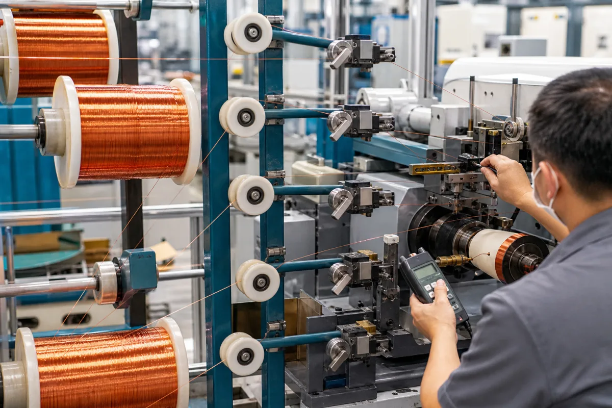
Wire tensioning system for wires-in-hand stator coil winding: a reel, brake and tension sensor for each parallel strand, and how each strand is checked
Multi-strand (wires-in-hand) stator coil winding · one reel, brake and tension sensor per strand, closed-loop set point, hand-held checks per wire
When a stator coil is wound with wires in hand, each parallel wire comes off its own reel. If the strands leave the reels at different tensions, the coil comes out with some wires tight and others loose. This page is about the system that holds every strand at a set tension: a brake and a tension sensor on each reel, a controller that closes the loop, and a way to check each wire on the machine.
Tensioning systems that feed two or more enamelled wires in parallel (wires in hand) to stator coil loopers and coil winders for distributed windings: per-strand dereelers or creels, reel brakes and clutch-brakes, tension sensing levers and load cells, set-point controllers, wire straightening on the way to the winder, and the hand-held meters used to check each strand. Single tensioner units as catalogue items, with their tension windows by model, are covered on the Wire tensioner for coil winding page; pay-off stands with dancer arms for spring coilers and wire benders on the Wire pay-off tensioning system page; coil winding machines for transformers on the Transformer winding machine page and needle and flyer winders for BLDC stators on the Concentrated-winding stator winding machine page. Spindles of coil winders are covered on the Winding spindle assembly page and wire length counting on the Counter system for cable and wire length page.
CNFX editorial research · Sources checked October 13, 2026 · 3 sources
Two or three wires tight, one or two nearly loose: how tension spreads across four strands wound in hand
Westinghouse's patent US 4,381,852 (filed 1982) describes the problem from the shop floor. Stator coil loops are wound around two pins, and the wire's own tension forms the 180° bends at the pins and keeps the sides straight between them. With four wires in parallel, the patent says operators spend time and waste copper trying to set the tension of each of the parallel wires, and the loops come out with two or three wires very tight and one or two nearly too loose. [1]
The patent names three causes. The reel brakes it describes, from a spring-loaded rope around a grooved steel rim to spring-loaded pressure plates and air-cylinder drum brakes, are set by feel with no calibration of friction force against adjustment. The braking force changes as the brakes heat up. And even at constant braking force, tension rises by about 60 % as the wire is unwound from about 22 in down to 14 in reel diameter. Variation in tension changes the loop shape, and excess tension makes insulation damage more likely. [1]
Editorial calculation: with constant brake torque, wire tension is torque divided by the radius the wire leaves from, so going from a 22 in to a 14 in diameter multiplies tension by 22/14, about 1.57, consistent with the patent's "about 60%". On four reels unwinding at different rates, each strand sits at a different point on that curve unless each reel has its own control.
Ask how many strands the system feeds, whether each strand has its own brake and sensor, and how tension is held as each reel goes from full to empty.
02
A load-cell lever with nine pulleys and a magnetic-powder clutch-brake: closing the loop on a 400–500 lb reel
In the Westinghouse system each wire runs from its own dereeler through a tension-sensing structure and a guide of horizontal and vertical rolls to the looper. The tension signal from a strain-gauge load cell goes to an error detector, and a control circuit sets the current to a magnetic-powder clutch-brake that restrains the reel through a chain and sprockets. [1]
The pulley spacing on the sensing lever is chosen so the wire is not bent plastically over each pulley; the patent warns that small pulleys spaced further apart at high tension would cold-work the copper and make it hard and springy. The single large reverse bend straightens the set the wire takes on the reel and reduces bulging of the straight sides of the loop at lower tension. [1]
Response speed is set to a medium rate: the patent reports that early tests gave serious tension oscillations and wire jerking even with manual open-loop control from a meter reading, and that the control has to reach the set tension before the first turn is completed around a knuckle pin without overcorrecting for the reel's starting inertia. The brake part of the clutch-brake damps those oscillations. [1] Editorial calculation: 100 lb of wire tension is about 445 N.
Element in US 4,381,852
Stated value or arrangement
Reel
About 400 lb of wire; bearings allow reels up to 500 lb [1]
Preferably nine closely spaced pulleys on a radius of about 21 in, giving one reverse bend on an effective radius of about 22 in, with a strain-gauge load cell [1]
Torque split
Clutch about 70 %, brake about 30 % of tensioning torque [1]
Torque at the reel
Clutch-brake rated 10 ft-lb, 6:1 chain ratio, 90 ft-lb at the dereeling shaft [1]
Stop and start
Tension drops to a lower reset value when the looper stops, after a delay of a fraction of a second, and returns to the set value when looping starts [1]
Ask for the tension range per strand, the sensor type and position, the brake or clutch-brake used, the response setting, and what the system does to tension when the winder stops and restarts.
03
Checking each strand on the machine: 0.3 to 2,000 cN hand-held meters against recommended winding tension by wire size
Westinghouse's patent notes that operators without a measuring system could only judge wire tightness by pulling on the wires. [1] Hans Schmidt lists hand-held electronic tension meters for winding machines, each with a stated copper-wire diameter limit for its measuring head. [2]
The set point for each strand comes from the wire. Elektrisola's NEMA metric data sheet for copper magnet wire lists a recommended winding tension per size: 1,450 g for 24 AWG (0.511 mm nominal bare), 630 g for 28 AWG (0.320 mm) and 400 g for 30 AWG (0.254 mm). [3]
Editorial calculation: 1,450 g is about 1,422 cN and 630 g about 618 cN. A 0.511 mm wire is just above the Ø 0.5 mm stated for the ETX and its tension is inside the ETX's 3–2,000 cN top range; 630 g on 28 AWG is above the ZED's 500 cN top range. [3][2]
Including Cu winding; guide rollers up to 2,000 m/min [2]
Give the wire size and insulation build of each strand and the number of strands, so the set point and the meter range can be fixed for the whole set.
04
Data for a multi-strand tensioning system
Paste it into your enquiry below or into an email to a maker, then replace every bracket.
Strands: [number in hand; wire size and insulation build; copper or aluminium]
Reels: [weight; full and empty diameter; creel layout]
Tension: [set point per strand; allowed difference between strands; recommended value from the wire supplier]
Brake: [friction, magnetic-powder clutch-brake, hysteresis or servo; one per strand]
Sensing: [load cell or dancer; position; display per strand]
Control: [closed or open loop; response setting; reduced tension at stop]
Winder: [looper or coil winder type; speed; start-stop cycle]
Checking: [hand-held meter model and range]
Explore company information and manufacturing capabilities, then discuss the scope of your project with a relevant supplier.
Share this page
Compiled and source-reviewed by the CNFX editorial team.
Each manufacturer above links to the page on that company's own website where the product is listed, with the date we checked it. How we source and review
· Page last updated 13 October 2026
Buyer questions
Why do parallel wires end up at different tensions in a stator coil?
US 4,381,852 attributes it to reel brakes set by feel, brakes changing as they heat, and tension rising about 60 % as a reel unwinds from 22 in to 14 in diameter. [1]
How is tension controlled on each reel?
In the Westinghouse system a strain-gauge load cell on a pulley lever measures each wire, and a magnetic-powder clutch-brake on the reel supplies about 70 % of the torque from the clutch and 30 % from the brake. [1]
Which hand-held meter checks a 0.5 mm winding wire?
Hans Schmidt lists the ETB and ETX for Cu wire up to Ø 0.5 mm, with ranges up to 3–2,000 cN. [2]
What winding tension is recommended for 24 AWG copper magnet wire?
Elektrisola's NEMA metric data sheet lists 1,450 g for 24 AWG (0.511 mm nominal bare diameter). [3]
Sources and what still needs a direct check
Sources checked 2026-10-13. Westinghouse's stator-coil tensioning patent (strand-to-strand tension spread, reel diameter drift, load-cell lever and clutch-brake), Hans Schmidt's winding-machine tension meter listing (ranges and wire limits), and Elektrisola's NEMA metric magnet wire data sheet (recommended winding tension by size).