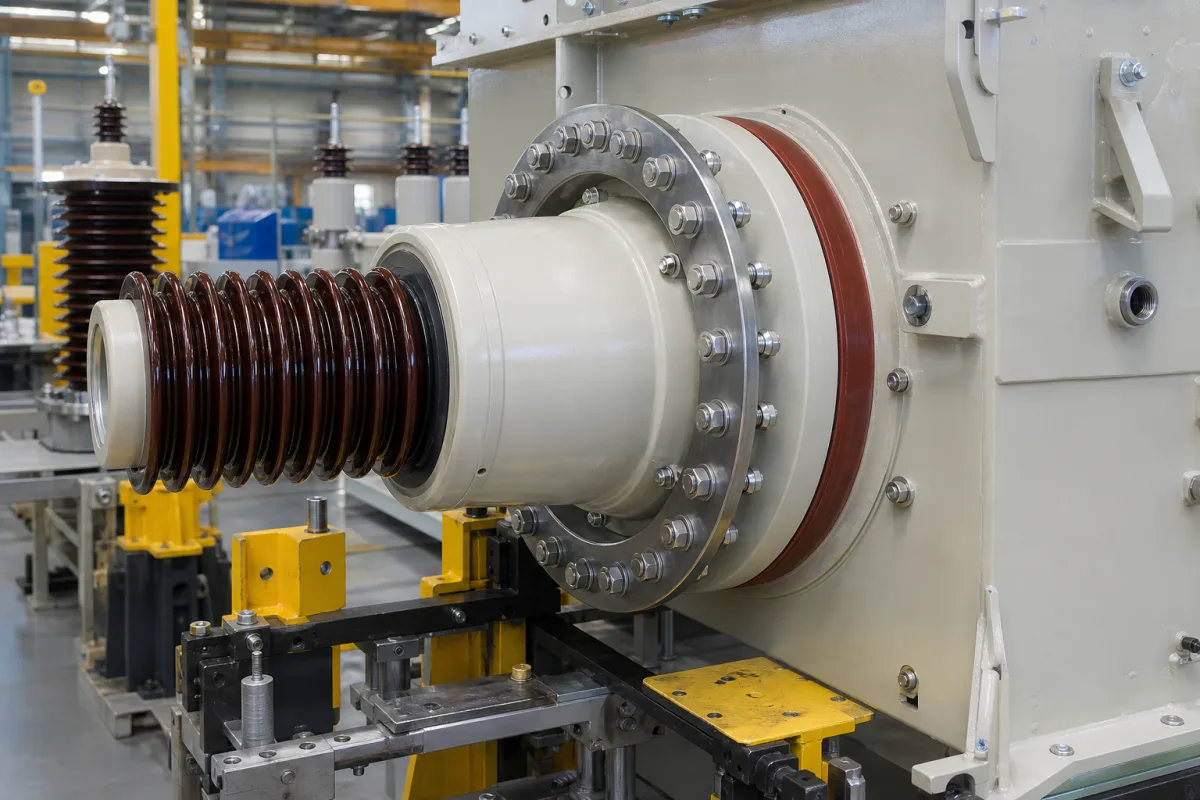
Flange assembly (the mounting flange that seats and seals a high-voltage bushing on a transformer tank)
Mounting flange assemblies of high-voltage transformer bushings · flange outside diameter, bolt circle and holes, sealing face, O-rings and flat gaskets, de-aeration hole, test tap, crosswise bolting, flange earthing and tightness checks
Every condenser bushing carries a metal mounting flange: it bolts to the transformer cover or turret, seals the oil in, carries the test tap and is earthed to the tank. Order it by the dimensions that must match the tank opening, the sealing arrangement between flange and tank, and the bolting, earthing and leak-test steps the installer will follow.
Mounting flanges of high-voltage transformer and reactor bushings as an assembly: flange dimensions and bolt pattern, sealing face and gaskets to the tank, de-aeration and test-tap fittings on the flange, bolting, earthing and tightness checks. The bushing as a whole (insulation, ratings, C1 and C2 trending) is covered on the High-voltage insulating bushing page; forged pipe flanges to ASME B16.5 on the Forged steel flange page; the transformer itself on the Power transformer page.
CNFX editorial research · Sources checked October 12, 2026 · 5 sources
Flange dimensions that have to meet the tank opening
PCORE (Hubbell) publishes flange data for each POC transformer bushing. Its 345 kV, 1175 kV BIL model POC1175G0800S has an aluminium flange of 23.00 in outside diameter with 12 mounting holes of 1.25 in on a 21.00 in bolt circle, a sealing surface outside diameter of 19.62 in, and 51.00 in of bushing below the flange. [1] Its 138 kV, 650 kV BIL model POC650G0800S has a 16.25 in flange with 6 holes of 1.25 in on a 14.25 in bolt circle and a 12.88 in sealing surface. [2]
Editorial calculation of hole spacing along the bolt circle: π × 21.00 in ÷ 12 ≈ 5.50 in on the 345 kV flange and π × 14.25 in ÷ 6 ≈ 7.46 in on the 138 kV flange. [1][2]
Send the bushing maker the tank or turret drawing (opening, stud or bolt pattern, sealing face) and ask for the flange drawing in return before either part is machined.
02
Sealing face, gaskets and the fittings on the flange
GE's erection instructions for its RIP bushings say "The sealing area between the bushings flange and transformer tank should be free of corrosion", that O-rings or flat gaskets are suitable, and that the de-aeration hole at the flange plate must not be covered by the sealing. They add: "The screw connection should be designed for not deforming the flange." Eyebolt threads that would project below the flange on the sealing side have to be removed. [4][3]
On GE's PCTR bushing, "The flange is mounted and glued onto the insulation core to have it oil tight", with two O-ring gaskets in the flange sealing its inner side against oil from both sides. The flange also carries the measuring tap: the test layer is insulated from the flange, splitting the capacitance into C1 and C2, and "The maximum permissible permanent voltage between the test layer and the flange is 1.5 kV." [4]
ABB's GOM guide places an oil sampling valve on the flange and requires the transformer oil level to be "Not lower than 30 mm from the bushing flange". [5]
03
Bolting the flange, earthing it and checking the seal
ABB's installation and maintenance guide for GOM bushings warns that where there is a space under the flange, "the bolts must not be tightened until the flange will crack"; the torque has to be set from the bolt size and cover design, and the bolts tightened "evenly crosswise in order to avoid damages to the flange". [5]
Once the bolts are tight, the flange is earthed through its M12 tapped hole, either with a greased pointed set screw tightened to 40 Nm to bite through the tank paint, or with a flexible cable from the M12 hole to the transformer, again tightened to 40 Nm, "This prevents electrical discharges between bushing flange and transformer tank under normal service conditions." [5]
For the seal between transformer and flange, the guide refers to the erection company's methods and gives a simple check on an oil-filled transformer with chalk or paper strips. [5]
Agree with the bushing maker and the transformer builder who sets the flange bolt torque, the gasket type and compression, the earthing method and the tightness test before erection.
04
Bushing flange order details
Paste it into your enquiry below or into an email to a maker, then replace every bracket.
Bushing: [type; kV; BIL; current]
Flange: [outside diameter; bolt circle; holes; material]
Tank side: [opening; studs or bolts; sealing face; turret drawing]
Seal: [O-ring or flat gasket; material]
Fittings: [de-aeration; oil valve; test tap]
Bolting: [size; torque; sequence]
Earthing: [M12 screw or cable]
Tests: [tightness method]
Explore company information and manufacturing capabilities, then discuss the scope of your project with a relevant supplier.
Share this page
Compiled and source-reviewed by the CNFX editorial team.
Each manufacturer above links to the page on that company's own website where the product is listed, with the date we checked it. How we source and review
· Page last updated 13 October 2026
Buyer questions
What flange data do I need to match the tank?
Flange outside diameter, number and size of holes, bolt circle and sealing surface diameter; PCORE lists these for each POC bushing. [1][2]
Can the gasket cover the de-aeration hole?
No. GE's instructions say the sealing must not cover the de-aeration hole at the flange plate. [3][4]
How hard should the flange bolts be tightened?
ABB's GOM guide sets torque by bolt size and cover design, tightened evenly crosswise, and warns against tightening until the flange cracks. [5]
Why earth the flange?
ABB says earthing prevents electrical discharges between bushing flange and transformer tank in service. [5]
Sources and what still needs a direct check
Sources checked 2026-10-12. PCORE (Hubbell) publishes specification sheets for POC bushings; GE Vernova publishes erection instructions for its RIP bushings; ABB's GOM installation and maintenance guide is read from a copy on manualsnet.com.