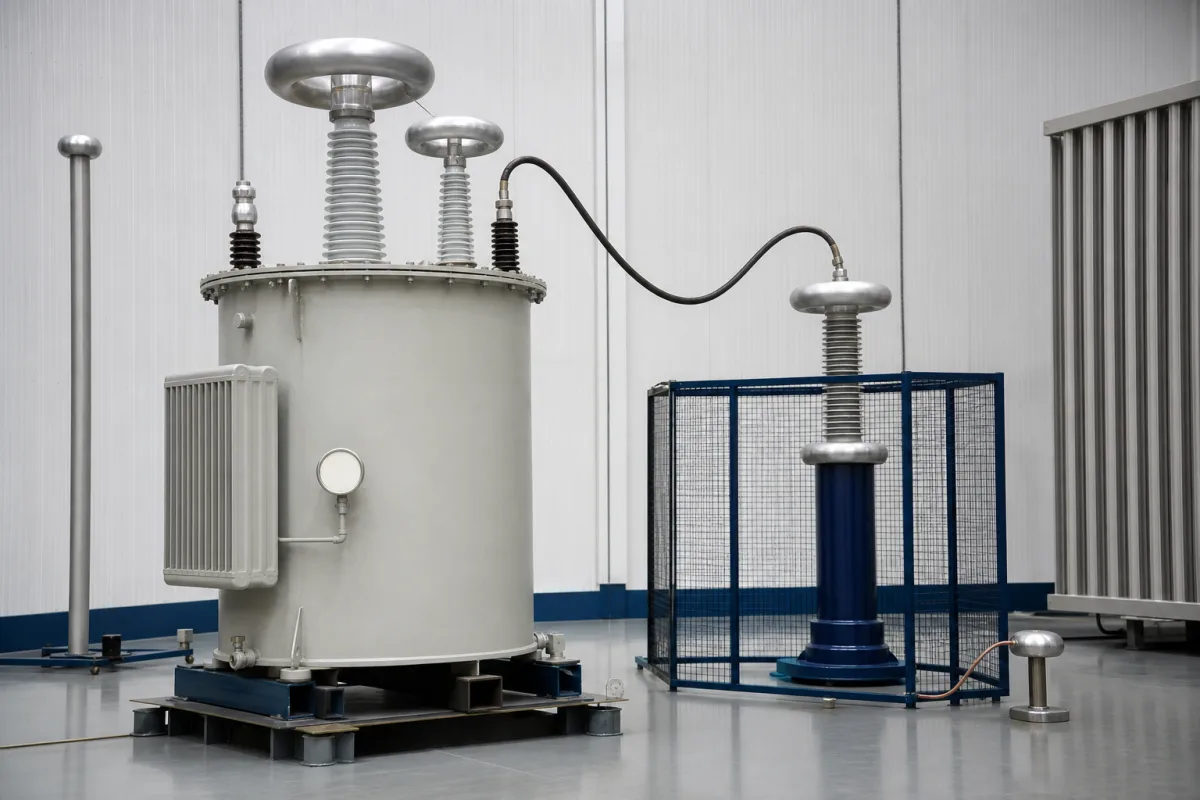
High-voltage AC test transformers and dielectric test sets · Output kV and current against test-object capacitance, kVA rating, duty cycle, partial-discharge level, regulator, reactor and coupling capacitor, measurement accuracy and safety interlocks
A high-voltage test transformer is the step-up transformer at the heart of an AC dielectric (hipot) test system, fed from a regulating transformer and controller, that applies a controlled high voltage to cables, transformers, bushings, switchgear, insulators and other apparatus to prove their insulation, with partial-discharge and capacitance measurement where the test requires it. Ask three things first: what test voltage and current the largest test object needs, what duty cycle and partial-discharge level the tests require, and which control, measurement and safety functions come with it.
AC high-voltage test transformers and complete AC dielectric test sets for factory, laboratory and field testing of electrical apparatus, including regulator, controls, compensating reactors and coupling capacitors. Resonant test systems, DC and VLF test sets, impulse generators, power and distribution transformers for service and instrument transformers are outside this page except where compared.
CNFX editorial research · Sources checked October 12, 2026 · 4 sources
Hipotronics' 700-DI series data sheet lists AC dielectric test sets for tests in accordance with IEC 60, IEEE 4 and IEC 270 (as the data sheet names them) and other national standards. The 2 kVA models give 5 kV at 400 mA, 10 kV at 200 mA, 15 kV at 133 mA, 30 kV at 66 mA and 50 kV at 40 mA from a 90–264 V supply; the 5 kVA models give 5 kV at 1,000 mA up to 100 kV at 50 mA from 200–264 V. They operate from 0.5% to 100% of rated voltage with rated current available across the range. [1]
Haefely's PSK data sheet describes tank-type AC test transformers of 200–1,000 kV for medium-capacitance objects and for tests needing stable voltage under changing load, such as heavy corona, wet and pollution tests, or inductive loads; ratings run from PSK 200-300 (200 kV, 300 kVA) to PSK 900-900, used with regulating transformers, compensating reactors and coupling capacitors, with oil-air or oil-SF₆ bushings and a top electrode for partial-discharge-free operation to rated voltage. [2]
The test methods behind these sets are defined in IEC 60060-1, High-voltage test techniques — Part 1: General definitions and test requirements. The IEC webstore lists edition 3.0 (IEC 60060-1:2010, 149 pages, from technical committee TC 42) as covering dielectric tests with alternating, direct and impulse voltage and their combinations, for equipment with highest voltage Um above 1 kV; it replaced the 1989 edition, moved artificial pollution tests to IEC 60507 and impulse current measurement to IEC 62475, and gave atmospheric correction factors as formulas. The same page shows a withdrawal date of 17 April 2025 for that edition, so name the current edition in the order. [3]
Editorial note: the Hipotronics data sheet names IEC 60 and IEC 270 rather than current edition numbers, so ask each supplier which edition of IEC 60060-1 and of IEEE 4 its voltage measurement and accuracy claims refer to. [3][1]
Editorial calculation: test current for a capacitive object is I = 2πfCV; at 100 kV and 50 Hz a 1.5 nF object draws about 2π × 50 × 1.5 × 10⁻⁹ × 100,000 ≈ 47 mA, within a 100 kV/50 mA (5 kVA) set, while a 10 nF object would draw about 314 mA (31 kVA) and need a larger transformer or a compensating reactor. Ask the supplier to size kVA from your largest test-object capacitance.
Give the supplier the test objects and their capacitance, maximum test voltage and frequency, test standards, duty cycle and test duration, partial-discharge level required, measuring functions (kV, mA, PD, tan δ), supply voltage, indoor or outdoor and mobile or fixed installation, safety interlocks, HV connections and quantities.
02
Check duty cycle, partial discharge, measurement and safety
The Hipotronics data sheet gives a duty cycle of 15 min on/45 min off six times a day for all-in-one cabinets and 1 h on/1 h off six times a day for separate components, or continuous at 90% rated voltage and 75% rated current; voltage and current measurement accuracy of ±1.5% of reading ±0.2% of full scale; a partial-discharge baseline of ≤20 pC up to full voltage for oil-insulated transformers (to be specified at order); adjustable overload from 10% to 110% of rated current; and a zero-start interlock that keeps voltage control at minimum before HV can be energised. [1]
Haefely's data sheet states: “Usual system duty cycle is 1 Hour ON, 1 Hours OFF, 2 times per day”, with duty extendable by radiators or forced oil cooling, an acoustic noise level below 65 dBA, and optional Buchholz or DGPT2 protection relays on an external oil expansion vessel. [2]
Editorial note: match the duty cycle to your longest test, such as long-duration withstand or partial-discharge tests, and confirm the partial-discharge level of the complete set-up, including connections and coupling capacitor, not just the transformer.
For portable sets used in the field as well as the laboratory, Doble's Phenix 6CP and 6CB line covers 15–200 kV with a combined control and regulator enclosure and a separate high-voltage section: an oil-insulated high-voltage transformer in an isolating cylindrical housing on a steel base, with a corona-free aluminium shielding electrode on the output, which Doble links to the line's partial-discharge performance. A guard mode measures specimen leakage current while bypassing stray capacitive currents. Safety features listed include a zero-start interlock, an external interlock provision, a locking emergency-off button, an external warning-light circuit and an overload circuit adjustable from 10% to 110% of rated current; the 6CB adds automatic voltage control, an adjustable rate of rise in volts per second, breakdown and maximum-voltage memory voltmeters and a 7-inch touch screen. Rated environmental conditions are 10–40 °C indoors or outdoors in fair weather, humidity below 95% non-condensing and altitude below 1,000 m (3,300 ft); a PD test certification and ISO 17025 calibration are offered as options. [4]
03
Armoured SF6 gas-insulated sets beside 50 kV and 100 kV units
Sute lists armoured SF6 gas-insulated test transformers next to impulse voltage and current generators; Xuming lists 50 kV and 100 kV models at 5 kVA and 10 kVA, a size range to check against the capacitance calculation above.
04
Regulating transformer, reactor, coupling capacitor and HV electrode
The compensating reactor is the alternative to a bigger transformer when test-object capacitance pushes current past the set's rating, as in the 10 nF example above. [2]
Voltage, kVA, duty, PD and accuracy figures across three test-set ranges
Size kVA from your largest test-object capacitance first; the duty-cycle and partial-discharge rows then show whether a set can hold that voltage for your longest test. [1]
2 companies list this product among what they make. Company figures are quoted from each
company's own website; every card states where the relationship came from.
Yangzhou Sute Technology Co., Ltd.
Manufacturing site to be confirmed for the order
Lists armoured SF6 gas-insulated test transformers alongside impulse voltage and impulse current generators.
Product scope checked 2026-10-12
SF6 gas test transformer product page · profile compiled by CNFX from public sources
Explore company information and manufacturing capabilities, then discuss the scope of your project with a relevant supplier.
Share this page
Compiled and source-reviewed by the CNFX editorial team.
Each manufacturer above links to the page on that company's own website where the product is listed, with the date we checked it. How we source and review
· Page last updated 13 October 2026
Buyer questions
What voltage and current do AC dielectric test sets provide?
One range runs from 5 kV at 400 mA (2 kVA) to 100 kV at 50 mA (5 kVA); tank-type systems from another supplier reach 1,000 kV. [1][2]
What duty cycle do AC test sets have?
One range is rated 1 h on/1 h off six times a day for separate components, or continuous at 90% voltage and 75% current. [1]
What partial-discharge level can a test transformer achieve?
One supplier gives a ≤20 pC baseline up to full voltage for oil-insulated transformers, specified at order. [1]
Which standard defines AC high-voltage test methods?
IEC 60060-1 covers AC, DC and impulse dielectric tests on equipment with Um above 1 kV; the 2010 edition lists a 2025 withdrawal date, so check the current edition. [3]
Can a high-voltage test set be used outdoors?
Doble rates its Phenix 6CP/6CB 15–200 kV AC dielectric test sets for 10–40 °C indoors or outdoors in fair weather, below 95% humidity non-condensing and below 1,000 m altitude. [4]
Sources and what still needs a direct check
Sources checked 2026-10-12. Hipotronics, Haefely and Doble (Phenix) describe their own systems and are used here to show what a test transformer specification covers; the IEC webstore abstract outlines IEC 60060-1. Ratings for your tests must come from the supplier's data and factory tests.