Power electronics · Voltage and current ratings with their temperatures, thermal resistance, switching losses and safe operating area
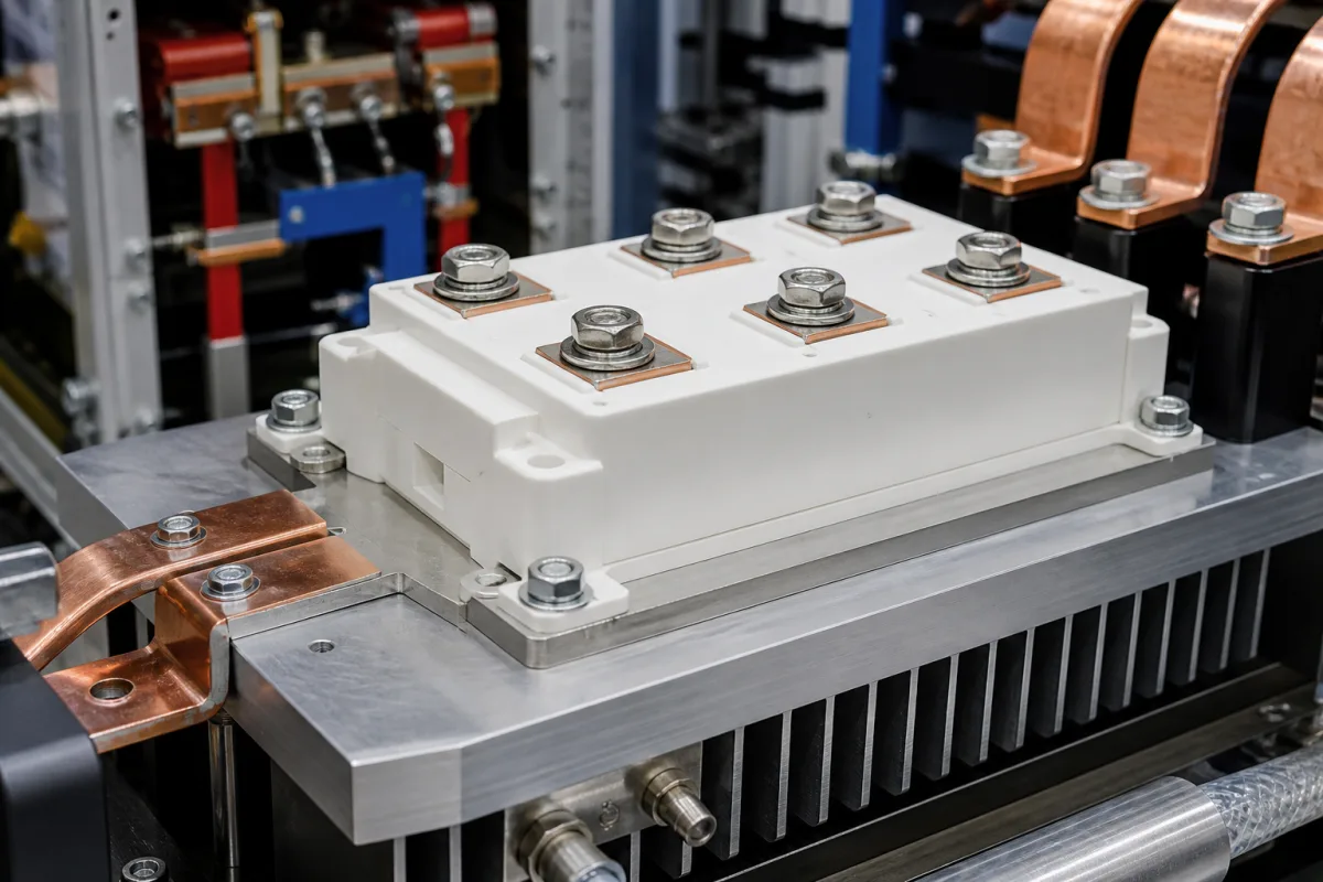
An IGBT module packages insulated-gate bipolar transistors and diodes on an insulated substrate for high-power switching in drives, inverters and power supplies. Ask three things first: the DC-link voltage and peak current, the switching frequency and cooling, and the package and gate-drive interface.
IGBT power modules (half-bridge, chopper, six-pack and PIM) and their datasheet ratings. Discrete IGBTs, gate drivers, complete inverters and products that merely use IGBTs are outside this page.
CNFX editorial research · Sources checked October 12, 2026 · 4 sources
Read voltage and current ratings with their conditions
Infineon's application note on industrial IGBT module datasheets explains that the permissible collector-emitter voltage VCES is specified at a junction temperature of 25 °C and decreases at lower temperatures; that the DC collector current rating is calculated from the total power dissipation, so the junction and case temperatures must be stated, and current ratings without defined temperatures have no technical meaning; and that the repetitive peak collector current allows the nominal rating to be exceeded briefly, with the datasheet value lower than theory because bond wires, busbars and connectors also limit it. [1]
Duken, a supplier listed here, states its module ranges as 650–1,700 V and 15–1,600 A and gives current at 100 °C: for example, DKG20PI60TE is listed at 600 V, 20 A at 100 °C, 1.65 V VCE(sat) at 25 °C and 5.25 V gate threshold. [2] Compare modules only at the same stated temperatures.
A full module data sheet shows how these ratings sit together. SEMIKRON's SKM400GB12E4 (SEMITRANS 3 half-bridge, IGBT4 and CAL4 diodes, Rev. 4, 2013) gives VCES 1,200 V at 25 °C; IC 616 A at Tc 25 °C and 474 A at Tc 80 °C with Tj 175 °C, against a nominal 400 A; ICRM 1,200 A; a 10 µs short-circuit withstand at 800 V and 150 °C; isolation of 4,000 V AC for 1 minute; case temperature limited to 125 °C and a recommended operating junction range of −40 to +150 °C. [3]
Give the supplier the topology, DC-link voltage, RMS and peak currents, switching frequency, modulation, cooling method and heatsink temperature, package and mounting, gate-drive voltage and resistance, and required lifetime or power cycling.
02
Check thermal resistance, losses and safe operating area
The note describes total power dissipation Ptot as the maximum that can pass through the junction-to-case thermal resistance RthJC, set by the temperature difference between junction and case. Switching energies Eon and Eoff are given per pulse and depend strongly on the gate drive, layout, gate resistance, voltages, currents and junction temperature, so datasheet values only indicate performance in a specific test setup. At turn-off, the chip can switch up to twice nominal current within its blocking voltage, but the module's reverse-bias safe operating area is reduced by internal stray inductance, and voltage spikes must not exceed the rated voltage. [1]
Editorial calculation: dissipation = temperature difference ÷ RthJC. With a junction allowed at 150 °C, a case at 80 °C and RthJC of 0.1 K/W (example values), 70 ÷ 0.1 = 700 W can be dissipated. [1] Use the module's actual RthJC and your heatsink temperature.
The same sheet lists VCE(sat) of 1.80 V (typ.) at 400 A and 25 °C and 2.20 V (typ.) at 150 °C; at 600 V, 400 A and 150 °C, Eon of 33 mJ and Eoff of 56 mJ per pulse, with diode recovery energy Err of 30.5 mJ; RthJC of 0.072 K/W per IGBT and 0.14 K/W per diode, and case-to-sink 0.02 K/W (typ.) per module. [3] It is rated for switching frequencies up to 12 kHz and weighs 325 g. [3]
Editorial calculation: switching at 5 kHz with those figures, one IGBT loses about (33 + 56) mJ × 5,000 ≈ 445 W in switching alone, plus conduction loss of roughly 2.2 V × the average current; at RthJC 0.072 K/W, 445 W raises the junction about 32 K above the case. Real losses scale with current, voltage and duty, so ask for a loss simulation at your operating point. [3]
Editorial calculation: conduction loss is roughly VCE(sat) × current while conducting; for the Duken example, 1.65 V × 20 A ≈ 33 W during conduction at 25 °C values, before switching losses and duty cycle. [2] Ask the supplier for loss simulation at your operating point.
03
Map voltage class to current rating and package
Hitachi Energy's IGBT and diode module range lists each part by VCES, IC, circuit type and package, in voltage classes of 1,200, 1,700, 2,300, 3,300, 4,500 and 6,500 V. The table groups its listed IGBT modules by voltage class; it shows how the highest current available in one package falls as voltage class rises. [4]
The same range lists phase-leg MOSFET modules in LinPak at 1,700 V (2 × 900 and 2 × 1,800 A), 2,300 V (2 × 900 and 2 × 1,800 A) and 3,300 V (2 × 480 to 2 × 1,000 A), and separate diode modules up to 3,600 A at 1,700 V. [4]
Editorial calculation: the highest listed single-IGBT rating falls from 3,600 A at 1,700 V to 1,800 A at 3,300 V, 1,500 A at 4,500 V and 1,000 A at 6,500 V; the product VCES × IC stays between 5.9 and 6.8 million V·A for those four parts. As Infineon's note explains, each IC is only meaningful with its stated case and junction temperatures, so compare those conditions on the individual data sheets before comparing parts across makers. [4][1]
IGBT modules, press-packs and discretes from module makers and component distributors on the linked sites
Greegoo lists IGBT modules from 600 V to 4,500 V; China Resources Microelectronics lists IGBT modules among its power devices; Duken lists half-bridge, chopper, PIM and 1,700 V modules; Hiitio lists IGBT modules and press-pack IGBTs; Sinesemi lists IGBT discretes and modules; YZPST lists IGBT modules with rectifiers; Anxinruo and GNS list IGBT modules among electronic components.
05
IGBT and diode chips, insulated substrate, baseplate, terminals and housing
The terminal row limits current as well as the chips: Infineon explains that the datasheet repetitive peak collector current sits below the theoretical value because bond wires, busbars and connectors also limit it. [1]
VCES, collector current at stated temperatures, RthJC, junction temperature, isolation, gate threshold and switching delays for a module order
The example values mix two modules, SEMIKRON's 1,200 V SKM400GB12E4 and Duken's 600 V DKG20PI60TE, so compare a quoted part only at its own stated temperatures and test setup; dimensions and humidity have no published value here. [3][2]
8 companies list this product among what they make. Company figures are quoted from each
company's own website; every card states where the relationship came from.
Explore company information and manufacturing capabilities, then discuss the scope of your project with a relevant supplier.
Share this page
Compiled and source-reviewed by the CNFX editorial team.
Each manufacturer above links to the page on that company's own website where the product is listed, with the date we checked it. How we source and review
· Page last updated 13 October 2026
Buyer questions
Why must IGBT current ratings state temperatures?
The current rating is calculated from power dissipation through the thermal resistance, so it depends on junction and case temperature; without them it has no technical meaning. [1]
Can I compare switching losses between IGBT datasheets?
Only roughly; Eon and Eoff depend on gate drive, layout, resistance, voltage, current and temperature in each maker's test setup. [1]
How much power can an IGBT module dissipate?
Junction-to-case temperature difference divided by RthJC; for example 70 K ÷ 0.1 K/W = 700 W. [1]
How much does a 1,200 V, 400 A IGBT module lose per switching cycle?
SEMIKRON's SKM400GB12E4 sheet gives Eon 33 mJ and Eoff 56 mJ at 600 V, 400 A and 150 °C. [3]
What voltage classes do high-power IGBT modules come in?
Hitachi Energy lists IGBT and diode modules at 1,200, 1,700, 2,300, 3,300, 4,500 and 6,500 V, with single-IGBT HiPak ratings from 3,600 A at 1,700 V down to 400–1,000 A at 6,500 V. [4]
Sources and what still needs a direct check
Sources checked 2026-10-12. Infineon is an IGBT maker; its application note explains how datasheet ratings are defined. SEMIKRON's SKM400GB12E4 data sheet shows one module's full set of ratings. Hitachi Energy lists its own module range by voltage, current and package. Duken is a supplier listed on this page; its values are catalogue figures.