Editorial Technical Reference

Industrial Electromagnetic Vibration Testing System

This page explains how Industrial Electromagnetic Vibration Testing System is classified within Manufacture of Other Electrical Equipment. Technical values and manufacturer relationships are research references; confirm the current specification and supplier evidence for each order.

Technical Definition & Core Assembly

Standalone electromagnetic vibration test machine for product durability validation

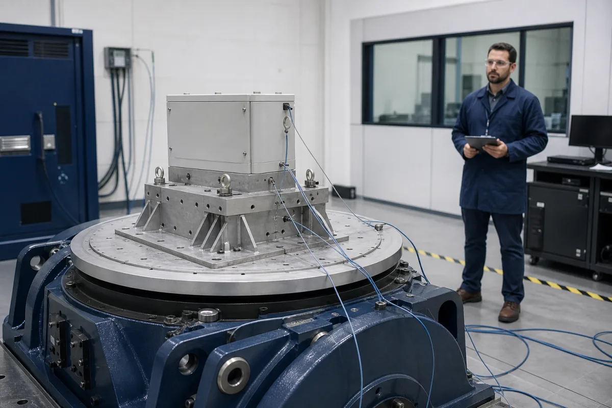
Industrial Electromagnetic Vibration Testing System in a manufacturing environment
Representative product image. Confirm appearance and specifications with the manufacturer.

Product Specifications

Technical details and manufacturing context for Industrial Electromagnetic Vibration Testing System

Definition
An industrial electrodynamic vibration test system is a configured combination of vibration generator, power amplifier, controller, transducers, fixtures and, where required, cooling, head expander or slip table. It generates a commanded motion so a separate specimen specification can be applied and measured. It does not itself define the specimen test severity, prove product durability or guarantee regulatory compliance. Force, frequency, displacement, velocity and acceleration are coupled limits: available performance changes with sine, random or shock mode, waveform, frequency, moving mass, fixture/specimen mass, centre of gravity, cooling and amplifier/exciter combination. Payload alone is not a dynamic rating. The page numbers are unverified category comparison prompts, not one coherent system specification. Verify the exact system curve, peak/continuous conventions, reference transducer, control strategy, facility services, installation loads, safety provisions and calibration evidence with the legal manufacturer.
Working Principle
Current from the power amplifier acts on a drive coil in a magnetic field and produces force on the moving assembly. The magnetic circuit may use field coils or permanent magnets; neodymium is not inherent to the category. A controller compares the commanded waveform with feedback from a reference transducer and adjusts drive within the system limits. The fixture and specimen alter total moving mass, resonances, overturning moments and force demand. At low frequency displacement can be limiting, at intermediate conditions velocity or force can dominate, and at high frequency acceleration, armature dynamics, fixture modes or amplifier voltage can limit performance. Sine, random and shock capabilities require their own declared conditions, control strategy and abort limits.
Common Materials
Conductive drive winding, Structural base and frame, Armature and suspension components, Model-specific magnetic circuit
Technical Parameters
ParameterTypical rangeNotes & selection driver
Maximum ForceRequired10–50 kNUnverified category prompt; state sine/random/shock, peak or continuous force, frequency, cooling, fixture, specimen and armature load
Frequency RangeRequired5–3000 HzUnverified category prompt; usable range depends on force, displacement, velocity, acceleration, payload, fixture, controller and mode
Maximum DisplacementRequired25–100 mmUnverified category prompt; declare single-peak or peak-to-peak convention, frequency, payload, fixture and mechanical-stop margin
Maximum VelocityRequired1–2 m/sUnverified category prompt; state peak or RMS convention and the frequency, displacement, payload, fixture and waveform conditions
Maximum AccelerationRequired50–100 gUnverified category prompt; acceleration capability is frequency-, force-, payload-, fixture-, armature- and waveform-dependent
Armature Mass5–20 kgUnverified category prompt; use the exact moving-element definition and include head expander or slip-table coupling where applicable
Maximum Payload100–500 kgUnverified category prompt; static payload alone does not establish dynamic capability—include fixture/specimen mass, centre of gravity, overturning moment and profile
Power Supply380 ±10% V ACUnverified category prompt; confirm complete amplifier, exciter, cooling and auxiliary supply voltage, phase, frequency, power and facility requirements
Operating Temperature0–40 °CUnverified category prompt; confirm exact system, cooling medium, heat load, altitude, humidity and manufacturer derating curve
Protection RatingEnclosure-dependentOnly a declared equipment enclosure has an IP code; identify the exciter, amplifier, controller, cooling unit or complete-system boundary
Control Accuracy±2 %Unverified headline; identify the controlled quantity, error definition, reference transducer, bandwidth, profile, load and controller settings
Noise Level≤75 dB(A)Unverified category prompt; state operating profile, payload, cooling, enclosure, measurement method, positions, background and uncertainty
Weight1500–5000 kgUnverified category prompt; define included amplifier, exciter, base, slip table, cooling and auxiliaries; obtain point loads and anchoring plan

Ranges are indicative industry figures for RFQ preparation, not a supplier commitment. Confirm every value and standard with the legal manufacturer before ordering.

Components / BOM
  • Moving Coil Assembly
    Generates electromagnetic force through current flow in magnetic field
    Material: Copper windings, aluminum former
  • Permanent Magnet Assembly
    Provides static magnetic field for coil interaction
    Material: Neodymium magnets, steel housing
  • Vibration Table
    Platform for mounting test specimens
    Material: Aluminum alloy
  • Power Amplifier
    Amplifies control signals to drive moving coil
    Material: Electronic components, aluminum housing
  • Cooling System Optional
    Dissipates heat from moving coil during operation
    Material: Aluminum fins, copper pipes

Industry Taxonomies & Aliases

Commonly used trade names and technical identifiers for Industrial Electromagnetic Vibration Testing System.

Industrial Ecosystem & Supply Chain Structure

Complementary Systems
Downstream Applications
Specialized Tooling

Application Fit & Sizing Matrix

Operational Limits
load: Build the moving-mass and moment budget from armature, expander/slip table, fixture, specimen, cables and centre of gravity.
test: Define specimen standard/specification, sine/random/shock profile, axes, duration, tolerances, control/monitor channels and abort limits.
facility: Confirm amplifier/cooling power, water/air, heat/noise, foundation/point loads, anchoring, guarding and enclosure boundaries.
measurement: Define reference/control transducers, mounting, calibration, uncertainty, sampling, filtering and profile verification.
performance: Check required force, displacement, velocity and acceleration simultaneously over frequency against exact system curves.
Sizing Data Required
  • Convert the required profile and total moving mass into force demand
  • Check fixture and specimen resonances with a structural assessment
  • Verify low-frequency displacement and high-frequency acceleration/fixture limits
  • Reserve margin for control, cross-axis motion and configuration uncertainty
  • Require an acceptance test on the delivered amplifier-exciter-controller combination

Reliability & Engineering Risk Analysis

Failure Mode & Root Cause
Profile cannot be reproduced within tolerance
Cause: One coupled force, displacement, velocity, acceleration, amplifier or control limit is exceeded after fixture/specimen loading.
Fixture, specimen or armature is damaged
Cause: Resonance, fatigue, overturning moment, loose attachment, excessive motion or an incorrect abort strategy was not controlled.
Measurement or control is misleading
Cause: Transducer mounting, calibration, cable motion, cross-axis response, saturation, filtering or control-point choice is unsuitable.
Maintenance Indicators
  • Rising distortion, notching, force/current/voltage limit, repeated abort or control-spectrum error
  • Changed suspension centring, armature rub, cooling flow/temperature, bearing/guide noise or cross-axis motion
  • Reference-channel drift, damaged cable/connector, calibration expiry or fixture response change
Engineering Tips
  • Run low-level resonance survey and verify the complete control/monitor chain before full profile.
  • Use reviewed fixture analysis, fastener procedure, mass/moment limits and conservative abort settings.
  • Maintain the exact amplifier, exciter, cooling, controller and transducer configuration with traceable records.

Indicative industry ranges for design and RFQ preparation. Confirm the exact figures and applicable standard with the manufacturer before specifying.

Compliance & Manufacturing Standards

Applicable Standards
ISO 5344:2004 specifies performance characteristics and performance test conditions for electrodynamic vibration-generator systems and identifies additional characteristics a manufacturer can declare. Calculated mixed-source system performance is less precise than measurement of the actual vibrator-amplifier system. IEC 60068-2-6:2007 is a sinusoidal-vibration procedure used to determine whether a specimen withstands specified severities. The relevant specification selects severity and acceptability; it is not a generic shaker rating or certification. ISO 5348 concerns mechanical mounting of accelerometers and does not establish shaker force, frequency, flatness or control accuracy. ASTM E1876 addresses elastic-property measurement by impulse excitation and is not general conformity evidence for an electrodynamic vibration test system. IEC 60529 applies an IP code to a declared enclosure boundary, not automatically to every subsystem.

Quoted from the published standard.

Manufacturing Precision
  • No universal ≤0.05 mm/m table flatness, ±0.5% frequency accuracy, 155 °C coil limit, 250 MPa yield limit, 3% THD trigger, 85 °C cutoff, 1 µm oil film, 0.5 bar lubrication or 4.5 mm/s alert threshold is asserted.
Quality Inspection
  • Verify the delivered system configuration and declared sine/random/shock performance under stated conditions.
  • Calibrate and document the reference/control transducers and measurement uncertainty.
  • Perform installation, safety, facility and acceptance checks with the final fixture and representative load.

Manufacturers of Industrial Electromagnetic Vibration Testing System

1 company lists this product among what they make. Company figures are quoted from each company's own website; every card states where the relationship came from.

HUDA Technology Pte. Ltd.
Yiyang, Hunan, CN
Listed on the company's own website · profile compiled by CNFX from public sources
Listed there as: “Electrodynamic Vibration Test System”
View source page ↗ hudatest.com · checked 2026-09-03

Manufacturer listings support early research and capability understanding. They are not certification, ranking, or transaction guarantees.

Share this page
Technical documentation
Request current drawings, revision history, and a signed specification sheet.
Manufacturing capability
Verify equipment lists, process limits, capacity, and representative production evidence.
Inspection readiness
Confirm test methods, calibrated equipment, sampling plans, and traceable reports.
Supplier transparency
Check the legal entity, factory address, ownership, certifications, and direct contacts.

CNFX does not score or rank suppliers. Buyers must verify all claims and documents with the legal manufacturer before ordering.

Frequently Asked Questions

Can the maximum force, displacement, velocity and acceleration all be used at the same time?

Usually not. Obtain the exact system performance curves and conventions. Frequency, waveform, moving mass, fixture/specimen, cooling and amplifier/exciter combination determine which limit is active.

Is maximum payload a complete dynamic rating?

No. Include armature, head expander or slip table, fixture and specimen mass, centre of gravity, overturning moments, resonances and the required profile.

Does IEC 60068-2-6 certify the vibration test system?

No. IEC 60068-2-6 provides a sinusoidal-vibration test procedure for specimens and relies on the relevant specification to select severities and acceptability. Equipment capability and verification need separate evidence.

What does ISO 5344 cover?

ISO 5344 specifies performance characteristics and test conditions for electrodynamic vibration-generator systems and lists characteristics a manufacturer can declare. It supports system selection but does not prove this page range without exact model evidence.

Does every component of the system have IP54–IP65?

No. An IEC 60529 IP code belongs to a declared enclosure. Identify whether it applies to the exciter, amplifier, controller, cooling unit or complete installation.

Data Basis

Editorial classification, named public sources where available, and source-reviewed manufacturer records.

Preliminary Technical Classification
This page supports structured research, RFQ preparation, and supplier evaluation. It does not replace buyer-led supplier qualification, standards review, or technical approval.
Buyer enquiry

Request manufacturing insight for Industrial Electromagnetic Vibration Testing System

Ask for use case, specification boundaries, supplier type, and RFQ preparation information for this product.

Where it goes
Straight to the CNFX editorial desk, and to the manufacturer if this product is linked to a claimed profile. Nothing is broadcast to a supplier list.
Your details stay here
We do not sell or rent enquiry data, and we do not add you to a mailing list. Used only to answer this request.
No commission, no middleman
CNFX is a directory. We take no cut of any order and never negotiate on a supplier's behalf.
What we don't claim
A listing is not an endorsement. Qualify every supplier and verify every figure yourself before ordering.

Your business information is used only to process this request.

Thank you! Your message has been sent. We'll respond within 1–3 business days.
Sorry, we couldn't send your message. Please try again, or email us at [email protected].

Need to Manufacture Industrial Electromagnetic Vibration Testing System?

Compare manufacturer profiles with relevant product and process capability.

Previous Product
Industrial Electromagnetic Relay Coil Assembly
Next Product
Precision Current Shunt Resistor
Get QuotesChat