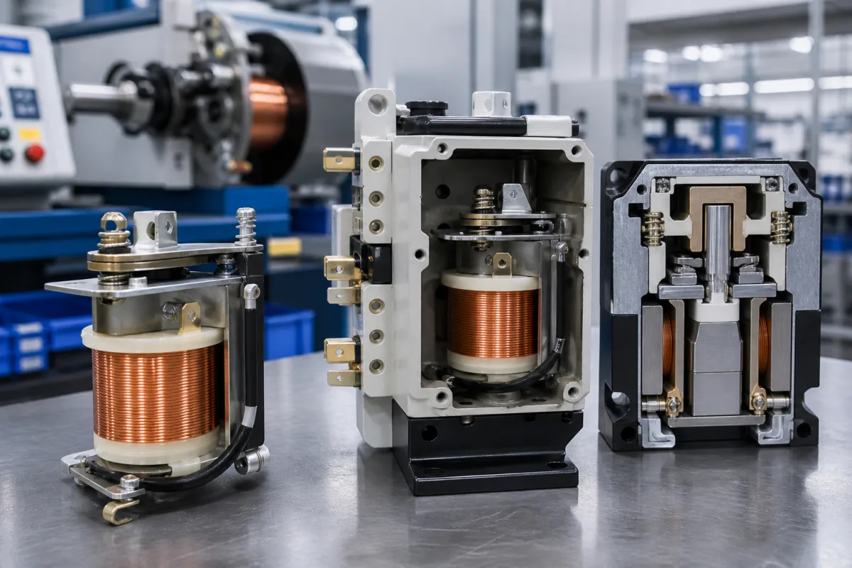
Relay coil assembly for industrial plug-in relays: winding resistance, ampere-turns and pick-up voltage when the coil is hot
The wound coil inside an industrial plug-in relay · resistance and current for each rated voltage, the 0.8–1.1 UN operating window, copper's 0.393% per °C and what a hot coil does to pick-up voltage
A relay coil assembly is the bobbin, the enamelled copper winding, the core and the terminations that turn a control voltage into the magnetic pull on the relay's armature. Every value a buyer sees for it, from resistance at 20 °C to pick-up and drop-out voltage, comes back to one quantity: the ampere-turns the winding delivers. Because copper resistance climbs with temperature, a coil that pulls in at 80% of its rated voltage when cold needs more when it has been energised for an hour.
The coil sub-assembly of electromechanical industrial and general-purpose relays (bobbin, magnet-wire winding, core and coil terminals) and its electrical data: resistance and current per rated voltage, operating range, holding and drop-out voltage, ampere-turns, wire thermal class and the effect of coil temperature on pick-up. Complete power relays, their contacts and load ratings are covered on the Power relay page; bus-switched relay output terminals on the Relay output module for remote I/O page; field coils for MR dampers on the Electromagnetic coil for magnetorheological (MR) dampers page; and breaker shunt releases on the Trip solenoid page. Contactor and solenoid-valve coils are outside this page.
CNFX editorial research · Sources checked October 12, 2026 · 4 sources
One relay, eight DC windings: 40 Ω at 6 V to 54 kΩ at 220 V for about 1 W
Finder's 55 series general-purpose relay takes the same 1 W DC coil power (1.5 VA AC) whatever the rated voltage; the winding is changed instead. Its current data sheet lists the DC coils below, each with an operating range of 0.8 to 1.1 UN, a DC holding voltage of 0.5 UN and a must drop-out voltage of 0.1 UN (0.2 UN on AC). [1]
Finder's 2003 data sheet for the same series states that resistance values relate to +20 °C with a tolerance of ±10% on resistance and current, and gives a nominal magnetomotive force of 200 ampere-turns for DC coils and 150 for AC, coil wire of thermal insulation class F (+155 °C) and a coil thermal resistance of 50 °C/W. [2]
Editorial calculation: at 24 V and 600 Ω the coil draws 24 / 600 = 40 mA, matching the table, and dissipates 24² / 600 = 0.96 W, the 1 W rating. At 200 ampere-turns and 40 mA the winding needs about 200 / 0.040 = 5,000 turns; the 220 V coil, at 4 mA, needs about 50,000 turns of much finer wire for the same pull. These turn counts are estimates from the published figures, not data from Finder. [1][2]
Insulation between coil and contacts on the current 55 series is basic insulation rated at 4 kV impulse (1.2/50 µs) and 2,000 V AC dielectric strength. [1]
State the control voltage and its tolerance, AC or DC, maximum ambient temperature at the relay, whether the coil stays energised continuously, and any suppression diode or LED needed across the coil.
02
Copper's 0.00393 per °C: why a warm coil needs more than 0.8 UN to pull in
NBS Handbook 100, the US copper wire tables, gives the International Electrotechnical Commission's 1913 standard temperature coefficient for annealed copper at 100% conductivity as 0.00393 per °C at 20 °C (0.00427 at 0 °C, 0.00385 at 25 °C), and notes that it would apply to the windings of instruments and machines, because winding and handling do not appreciably change the coefficient. [3]
TE Connectivity's US 10,418,214 explains the consequence for relays and contactors: the magnetic field is set by turns times current, the turns are fixed once the coil is wound, and with a fixed DC supply the current is set by voltage and coil resistance, which is specified at 20 °C. As the coil warms from its own current or the ambient, resistance rises and the current and field fall; too little current can make the relay actuate slowly with prolonged arcing or welded contacts, or not actuate at all. TE's patented answer regulates the coil voltage from a temperature sensor beside the coil to hold the current constant. [4]
Editorial calculation: a 55 series DC coil dissipating 1 W through a 50 °C/W thermal resistance rises about 50 °C above ambient when continuously energised at UN. Its resistance then grows by 1 + 0.00393 × 50 ≈ 1.20 times, so to deliver the same ampere-turns the pick-up voltage rises from 0.8 UN to about 0.96 UN; on a 24 V coil, from 19.2 V to about 23 V. This assumes the coefficient applies across the rise and that pick-up depends only on coil current. [2][3][1]
Editorial calculation: at the 2003 data sheet's maximum ambient of +70 °C, a 50 °C rise puts the winding near 120 °C, inside the class F (155 °C) wire rating. Finder publishes curves of DC coil minimum pick-up voltage against ambient temperature and of temperature rise against heating time for the series; use those curves rather than this estimate for a design. [2]
Ask the supplier for the pick-up voltage at your maximum ambient with the coil already hot, the coil's thermal resistance or temperature-rise curve, and the wire thermal class.
03
Bobbin, winding, core and terminals: what each sets in the coil data
Part
What it sets
Published value
Magnet-wire winding
Resistance, current and ampere-turns per rated voltage
200 ampere-turns DC, 150 AC [2]; 40 Ω to 54 kΩ across DC coils [1]
Control voltage, ambient and duty for a relay coil
Paste it into your enquiry below or into an email to a maker, then replace every bracket.
Coil: [AC or DC; rated voltage; supply tolerance]
Ambient: [minimum and maximum at the relay]
Duty: [continuous or intermittent energisation]
Pick-up: [required pick-up voltage with hot coil]
Drop-out: [maximum residual voltage on the coil line]
Insulation: [coil-to-contact impulse and dielectric test]
Options: [suppression diode; LED; wire class]
Explore company information and manufacturing capabilities, then discuss the scope of your project with a relevant supplier.
Share this page
Compiled and source-reviewed by the CNFX editorial team.
Each manufacturer above links to the page on that company's own website where the product is listed, with the date we checked it. How we source and review
· Page last updated 13 October 2026
Buyer questions
What resistance does a 24 V DC relay coil have?
On Finder's 55 series it is 600 Ω at 20 °C, drawing 40 mA, with a ±10% tolerance on resistance and current given in the 2003 data sheet. [1][2]
How much does coil resistance change with temperature?
For annealed copper NBS gives 0.00393 per °C at 20 °C, so a 50 °C rise increases resistance by about 20%. [3]
Why can a hot relay fail to pull in?
TE's patent explains that at fixed voltage a warmer coil draws less current, weakening the field that is set by turns times current; too little can slow actuation or prevent it. [4]
Sources and what still needs a direct check
Sources checked 2026-10-12. Finder's two data sheets for its 55 series give coil tables, ampere-turns, wire class and thermal resistance; the NBS copper wire tables give the temperature coefficient; TE's patent describes the temperature problem from the relay maker's side.