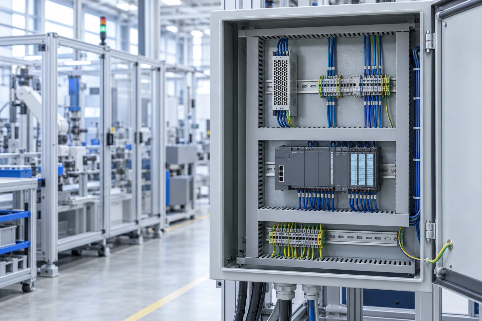
LIF240 is a series name: the 12 V model is 192 W, while the 24 V model is 240 W and the 55 V model is 242 W. For a control cabinet, choose the voltage first, then check continuous load, short peaks and the input/temperature derating curves. The model examples here use MORNSUN’s published R2 datasheet; they are not ratings for every DIN-rail supply.
CNFX editorial research · Sources checked October 9, 2026 · 11 sources
MORNSUN’s LIF240-10BxxR2 / -QQ datasheet, revision 2024.07.30-B/2, includes both coefficients and plotted curves. Unless stated otherwise, its measurements use 25 °C ambient, humidity below 75% RH, nominal input and rated output load. The unit uses free-air convection; a closed installation needs the maker’s application review [1].
Add up the continuous load
Sum the steady current of PLCs, I/O, sensors, relays and HMIs on the rail. Keep inrush and short peaks for the next step.
Check peaks against the boost window
The datasheet states 150% peak output for 3 seconds. Keep the peak amplitude and duration separate from the steady load, and obtain the permitted repetition/recovery duty from the maker; the sheet does not establish an unlimited sequence of 3-second boosts [1].
Apply temperature derating
At 230 VAC input, the 24, 48 and 55 V models lose 2.5% of output per °C between +60 and +70 °C; the 12 V model loses 1.25% per °C from +50 °C [1].
Apply low-line derating
The 115 VAC curve starts temperature derating at +45 °C, at 2.0% per °C. A separate curve, at 25 °C ambient, reduces output to 90% at 85 VAC or 120 VDC and reaches full output at 100 VAC or 140 VDC. The note requires derating at low input; do not invent a rule for multiplying or adding simultaneous derating factors [1].
Correct for altitude
Above 2000 m the permissible ambient temperature drops by 5 °C per 1000 m; the series is rated for operation up to 5000 m [1].
Leave the result with margin
Compare the derated capacity with continuous load and the specified peak duty. If capacity is insufficient, select a suitable larger supply or independently supplied circuits. Parallel connection of outputs needs an explicitly supported sharing or redundancy arrangement; it is not assumed for this series.
Example: 24 V / 10 A model
Derating applied
Usable continuous output
230 VAC, cabinet at 55 °C
None (below +60 °C)
240 W / 10 A
230 VAC, cabinet at 65 °C
5 °C × 2.5% = 12.5%
210 W / 8.75 A
115 VAC, cabinet at 55 °C
10 °C × 2.0% = 20%
192 W / 8.0 A
−40 °C ambient, nominal input
Curve shows 50% available output at −40 °C
about 120 W / 5 A for the 24 V model
The first three rows are arithmetic from the published slopes; the fourth reads the cold-temperature curve. They treat one stated condition at a time. The datasheet’s plots have been visually checked, but they do not establish a combined low-line/high-temperature/altitude formula or the acceptable boost repetition duty [1].
02
Choose the output voltage, then read the column that changes
The four listed voltage models use a metal case specified as 124 × 41 × 110 mm and a typical mass of 650 g. The sheet names AL5052 and SPCC for the case. Electrical values below retain their typ./max. distinction; efficiency is a typical value at 230 VAC under the stated test basis [1].
The 12 V model is not a 240 W unit
The 12 V variant is 192 W with typical output-voltage accuracy ±2.0%, compared with ±1.0% for the others. Its 230 VAC high-temperature derating starts at +50 °C rather than +60 °C. The 55 V entry is listed as 242 W. Quote the rating of the actual output variant, not the “240” in the family name [1].
Input specifications worth copying into your spec
The sheet lists 85–264 VAC or 120–370 VDC accepted input on the same terminals, but identifies 100–240 VAC as rated/certified input. Typical power factor is 0.98 at 115 VAC and 0.94 at 230 VAC; typical cold-start inrush is 15/30 A respectively. Leakage current is listed below 0.5 mA at 264 VAC. These input conditions must accompany the numbers [1].
QQ coating does not permit condensation
The QQ suffix denotes double-faced conformal coating. The same datasheet still prohibits wet locations and areas where moisture or condensation is expected. No exception for QQ is stated; do not use coating as permission to bypass that installation limit [1].
Model
Output
Adjust range
Efficiency typ., 230 VAC
Ripple p-p typ./max., 20 MHz
Max. capacitive load
Over-voltage trip
LIF240-10B12R2
12 V / 16 A (192 W)
12.0–14.0 V
92%
50 / 100 mV
160,000 µF
≤18 V
LIF240-10B24R2
24 V / 10 A (240 W)
24.0–28.0 V
94%
60 / 120 mV
40,000 µF
≤35 V
LIF240-10B48R2
48 V / 5 A (240 W)
48.0–53.0 V
94%
75 / 150 mV
10,000 µF
≤60 V
LIF240-10B55R2
55 V / 4.4 A (242 W)
52.0–56.0 V
94%
100 / 200 mV
10,000 µF
≤63 V
03
Separate the conversion blocks from the model’s serviceable interfaces
This is a functional reference, not a MORNSUN manufacturing BOM. TI’s 2017 TIDA-01494 industrial reference design illustrates the rectifier/PFC, isolated switching stage, synchronous output rectifier and feedback path. It is a different, 480 W design. The R2 datasheet identifies external terminals, controls and case, but does not disclose its internal component part numbers, counts or magnetic materials [4][1].
Component group
Role and supported evidence
Material / ordered-model boundary
Input filter and rectifier
Input filtering and AC rectification feed the power stage in TI’s reference design [4].
Filter/bridge part numbers and materials inside R2 are not published.
Power switching circuit
Semiconductor switches drive the conversion stage; active PFC is separately stated for R2 [4][1].
No R2 MOSFET, IGBT or controller identity is disclosed.
High-frequency transformer
TI’s isolated stage transfers energy across the isolation boundary [4].
R2 isolation ratings do not identify its core, winding material or topology.
Output rectifier and filter
TI’s example uses synchronous rectification and output capacitors [4].
That architecture is not proof of the rectifier type or capacitor specification inside R2.
Control and feedback circuit
TI’s block diagram shows output feedback through an optocoupler to the controller [4].
R2 controller/feedback parts and board layout remain unspecified.
Chassis and heat sink
R2 has a ventilated metal enclosure and free-air cooling [1].
Case materials are listed as AL5052/SPCC; no separate heatsink material or manufacturing quantity is disclosed.
Terminal block / connectors
The R2 drawing identifies input L/N/PE, DC output connections and DC OK contacts [1].
The sheet does not identify terminal polymer or contact alloy. Obtain connector and wire requirements for the order.
Protection circuits
R2 lists short-circuit, over-current, over-voltage and over-temperature responses [1].
Functions are specified; separate sensor/IC materials and a replaceable protection module are not established.
Do not open the R2 to identify these internal parts: its manufacturer prohibits opening or repair. Use the external drawing, ratings and report when selecting a replacement or checking an incoming unit [1].
04
Know how the unit behaves when something goes wrong
Fault behaviour decides whether a machine restarts on its own or needs a technician, so read these lines before choosing protection downstream.
Hiccup mode and large capacitive loads
The sheet specifies a maximum capacitive load by output voltage, including 40,000 µF for 24 V. Check the connected devices’ total input capacitance and startup demand with the maker; a boost-current statement does not remove the stated capacitive-load limit [1].
No hot plugging
The datasheet lists hot plug as unavailable [1], so plan maintenance with the input isolated.
DC OK is a threshold contact, not a diagnostic code
The relay is open below 90% of nominal output and closed when output is normal, with a maximum 30 VDC/1 A resistive-load contact rating. That contact alone does not identify overload, mains loss or overheating as the cause, nor specify how long the PLC remains powered. Confirm the monitoring input supply and failure response [1].
Short circuit
Hiccup mode: the unit runs constant current for 1 s, switches off for 10 s and repeats, recovering by itself within 10 s once the short is removed [1].
Overload
At 230 VAC, the datasheet’s over-current field states self-recovery at 110–200% of rated current for normal/high temperature and ≥105% at low temperature. These wide limits are not a selective-coordination design for downstream protection [1].
Over-voltage
Hiccup with self-recovery after the fault clears; the 24 V model trips at or below 35 V [1].
Over-temperature
A typical over-temperature-protection value of 80 °C is listed at 230 VAC and rated load. It is a protection datum, not permission for continuous operation at 80 °C or a guaranteed trip temperature [1].
DC OK relay
Contact rated 30 VDC / 1 A resistive; closed when output is normal and open when output falls below 90% of nominal [1]. Wire it to a PLC input to log supply faults.
Mains dip
Hold-up time is listed as a typical 20 ms value. The field provides no guaranteed minimum or explicit line/load condition beyond the sheet’s default test basis. It cannot establish an exact outage threshold for every cabinet; request the required hold-up test with input, load and acceptable output limit [1].
05
State the measurement basis alongside each electrical field
Nameplate values, typical test results and safety-test values answer different acceptance questions. These fields apply to the cited R2 example; limits for another supply require its own datasheet.
Parameter
Unit / example
Measurement basis or missing information
Input voltage range
VAC / VDC
Accepted 85–264 VAC/120–370 VDC; certified range separately stated as 100–240 VAC [1].
Output voltage
VDC
Nominal 12/24/48/55 V; use the ordered variant’s adjustment range and setpoint [1].
Rated output current
A
12/24/48/55 V entries:16/10/5/4.4 A. Apply the relevant derating curve [1].
Output power
W
192/240/240/242 W respectively; peak capacity is a separate 3-second statement [1].
Efficiency
%
Typical 92% for 12 V and 94% for other models at 230 VAC; the curves vary with input and load [1].
Operating ambient temperature
°C
−40 to +70 with derating. It is not case temperature or an output-power guarantee throughout the range [1].
Ingress protection
IP code
No IP rating is given in the R2 sheet read here. Class I is electrical safety classification, not IP protection; indoor/no-condensation use still applies [1].
Output ripple and noise
mVp-p
20 MHz bandwidth, tip-and-barrel and specified parallel test capacitors; typ./max. differ by voltage [1].
Line regulation
%
Typical ±0.5% at rated load. The field does not state a separate test sweep; agree the input test range [1].
Load regulation
%
Typical ±1.0% for 0–100% load; separate from output accuracy and ripple [1].
Withstand voltage
VAC / one minute
Input–output 3000, input–PE 2000, output–PE 500; test leakage below 15 mA. These are isolation-test values, not permissible working voltages [1].
Insulation resistance
MΩ
Minimum 50 at 500 VDC, ambient 25±5°C, relative humidity<95% without condensation, for the stated interface pairs [1].
MTBF
h / calculation method
>300,000 h, MIL-HDBK-217F at 25°C. No corresponding service interval or individual-unit lifespan is stated [1].
Dimensions
mm / drawing order
124×41×110 in the R2 sheet; use its mounting drawing. A different enclosure size cannot replace that drawing [1].
Weight
g
650 g typical for the listed R2 case; not a guaranteed shipped-carton mass [1].
06
Install it so the ratings still hold
Derating figures assume the mounting the maker describes. These installation conditions come from the same datasheet [1].
Above 50% permanent load, leave 20 mm above and below and 5 mm on each side; widen the side gap to 15 mm next to another heat source such as a second power supply [1].
Earth through the PE terminal on the input block, not a housing screw; the case must be connected to system PE in operation (safety class I) [1].
Use the specified copper-wire temperature rating: at least 90 °C for ambient ≤60 °C and at least 105 °C above 60 °C. Minimum insulation voltage is 300 V at input and 60 V at output. The wire note extends to 85 °C, but the product operating limit remains +70 °C with derating; wire selection does not expand it [1].
The series is designed for natural air cooling; for a closed environment the maker asks you to consult its application engineers [1].
Indoor use only, pollution degree 2, overvoltage category II; do not install where condensation can occur [1].
Output is trimmed with the ADJ potentiometer, clockwise to increase [1]; record the set voltage on the cabinet drawing.
The manufacturer instructs isolating input and preventing inadvertent re-energization before work, and prohibits opening, modifying or repairing the unit. Internal functional blocks below are selection context, not a repair procedure [1].
07
Verify the certificates yourself
The datasheet lists IEC 62368-1 safety approval with a CB report, EN 62368-1 and EN 61558-1, and states that the design refers to UL 61010-1, UL 61010-2-201 and UL 62368-1 [1].
The maker's own page flags its UL status
On 9 October 2026 the official LIF240 page still states that its UL certification after 1 May 2024 is currently invalid. This is the maker’s statement; CNFX has not checked an active UL file or report. If the purchase requires listing, obtain the current file, exact variant and covered use, and verify that record before relying on it [2].
Why 61010-2-201 appears on a power supply datasheet
The opened IEC entry is IEC 61010-2-201:2024 EXV, edition 3.0, published 24 October 2024. Its public summary says the control-equipment requirements supplement or modify IEC 61010-1:2010 with Amendment 1:2016. This publication postdates the July 2024 R2 datasheet; it is context for standard scope, not evidence that MORNSUN was tested to that edition. The standard text and product certification reports have not been read [3].
Certified input is narrower than accepted input
The rated input voltage given as certified is 100–240 VAC, while DC input is listed separately as 120–370 VDC [1]. If you plan to feed the unit from DC, ask whether DC operation is covered by the safety reports.
Ripple/noise is measured with 20 MHz bandwidth using the tip-and-barrel method and 47 µF electrolytic plus 0.1 µF ceramic capacitors in parallel at output. The sheet says its index-test methods follow company standards. Agree these conditions before comparing a report with the 24 V entry’s 60 mV typical /120 mV maximum figure [1].
08
Copy this RFQ and fill in the brackets
Paste it into your enquiry below or into an email to a maker, then replace every bracket.
Product: DIN-rail AC/DC power supply, quantity [pieces]
Output: [24 V] / [  ] A continuous, peak [  ] A for [  ] s, repeated every [  ] s
Input: [230 VAC / 115 VAC / DC  V]; lowest expected mains [  ] V
Cabinet: max ambient [  ] °C, altitude [  ] m, closed or ventilated [ ]
Signals: DC OK relay [required], contact rating [ ]
Capacitive load on output: about [  ] µF
Coating: [standard / QQ], indoor/non-condensing installation [ ]
Certificates required: [CB report IEC 62368-1 / UL listing with file number / CE / other]
Documents: datasheet revision, derating curve for the ordered model, guaranteed hold-up test conditions, ripple test method and batch report
Delivery to [country], target date [date]
5 companies list this product among what they make. Company figures are quoted from each
company's own website; every card states where the relationship came from.
MORNSUN
Guangzhou, China, and manufacturing centre (per official site; model site to be verified), CN
The current LIF240 page lists 12/24/48/55 V R2 models and links the six-page July 2024 datasheet used above. It still publishes the UL-invalidity notice checked on 9 October 2026. Obtain an exact variant, mounting/duty confirmation and current certification record; none is inferred from the family name.
Product scope checked 2026-10-09
Listed on the company's own website · profile compiled by CNFX from public sources
The official Moso selector separates LED-driver business from Jiama switching supplies, including adapters, PD chargers, custom boards and industrial supplies. This group-level range does not identify a DIN-rail model with the R2 ratings; confirm the supplying entity and exact mounting form.
Product scope checked 2026-10-09
Stated by the company · profile compiled by CNFX from public sources
Its QXP-PAD-24008000 page offers a 24 V/8 A desktop AC/DC adapter with flying leads, not the DIN-rail case described above. The product page gives 100–240 VAC input. No DIN mounting, DC OK relay or R2 boost/derating capability is established for that adapter.
Product scope checked 2026-10-09
Listed on the company's own website · profile compiled by CNFX from public sources
Listed there as: “industrial power supply solutions” View source page ↗qinxpsu.com · recorded 2026-09-07
Guangzhou Idealplusing Information Technology Co., Ltd.
Guangzhou, Guangdong, CN
Its site describes AC/DC supplies, DC/DC converters, inverters, adjustable supplies and rectifier systems. A named DIN-rail model was not identified on the page inspected. Confirm whether the proposed item is a finished cabinet supply, bench supply or another form; broad catalogue scope does not transfer the R2 ratings.
Product scope checked 2026-10-09
Listed on the company's own website · profile compiled by CNFX from public sources
Listed there as: “Industrial Power Supply” View source page ↗idealplusing.com · recorded 2026-09-15
Its Industrial Power Supply category lists MHB-FS AC/DC series from 35 to 350 W. The table has split 90–132/176–264 VAC input ranges while introductory copy describes a broader input range; request the exact model sheet. No DIN-rail mounting or independent approval was checked, and these are different products from R2.
Product scope checked 2026-10-09
Listed on the company's own website · profile compiled by CNFX from public sources
Listed there as: “Industrial Power Supply” View source page ↗jr-lighting.com · recorded 2026-09-07
Explore company information and manufacturing capabilities, then discuss the scope of your project with a relevant supplier.
Share this page
Compiled and source-reviewed by the CNFX editorial team.
Each manufacturer above links to the page on that company's own website where the product is listed, with the date we checked it. How we source and review
· Page last updated 13 October 2026
Buyer questions
How much power does a 240 W DIN-rail supply give at 65 °C?
For the 24 V model of the series reviewed, at 230 VAC input, derating of 2.5% per °C from +60 °C leaves about 210 W at 65 °C. Check the curve of the exact model you buy. [1]
Can the supply cover a motor or solenoid inrush?
The R2 datasheet states 150% peak load for 3 seconds. Check the actual peak current and duration; the permitted repetition/recovery duty is not established by that statement. [1]
What does the DC OK contact tell the PLC?
The R2 relay opens below 90% of nominal output and closes when output is normal. Its maximum rating is 30 VDC/1 A resistive. The contact does not identify the cause of low output or establish how long a PLC stays powered. [1]
Does the series reviewed have a valid UL certificate?
On 9 October 2026 the official product page still states that UL certification after 1 May 2024 is currently invalid. CNFX has not checked a current independent UL file. Obtain and verify a file covering the exact model and use before relying on listing. [2]
Sources and what still needs a direct check
Sources checked 2026-10-09. R2 numerical examples use MORNSUN’s six-page 2024.07.30-B/2 datasheet, including the visually checked derating plots and external drawing. TI TIDA-01494 is a separate circuit used only for functional explanation; selected pages 1–7 were read. The IEC entry supplies public standard scope, not a model certificate. Supplier pages show their stated ranges and product identities; inaccessible or mismatched records are identified above. Checks were made on 9 October 2026.
No internal MORNSUN manufacturing BOM, transformer material, PCB layout or repair specification was provided by the R2 sheet. TI’s reference circuit is a different design.
The derating graphs and coefficients have been read, but combined input/temperature/altitude derating, boosted-output repetition duty and guaranteed hold-up time require confirmation for the ordered model.
The maker still publishes a UL-invalidity notice. No current independent UL file, CB report or report covering DC input was checked.
The IEC entry is a public summary of the 2024 EXV publication. Neither its full standard text nor an exact edition covered by MORNSUN’s report was read.
No IP rating or permission for condensation was established; QQ coating does not override the datasheet’s installation prohibition.
Buyer enquiry
Request manufacturing insight
for Industrial Power Supply Unit
Ask for use case, specification boundaries, supplier type, and RFQ preparation
information for this product.
Where it goes
Straight to the CNFX editorial desk, and to the manufacturer if this product is
linked to a claimed profile. Nothing is broadcast to a supplier list.
Your details stay here
We do not sell or rent enquiry data, and we do not add you to a mailing list.
Used only to answer this request.
No commission, no middleman
CNFX is a directory. We take no cut of any order and never negotiate on a
supplier's behalf.
What to include
Share your product specifications, quantity, destination and target delivery date.
Need to Manufacture Industrial Power Supply Unit?
Compare manufacturer profiles with relevant product and process capability.