Editorial Technical Reference

Main Circuit Breaker

This page explains how Main Circuit Breaker is classified within Electrical Equipment Manufacturing. Technical values and manufacturer relationships are research references; confirm the current specification and supplier evidence for each order.

Technical Definition & Core Assembly

Primary protective device in a smart home electrical panel that controls and safeguards the entire electrical circuit.

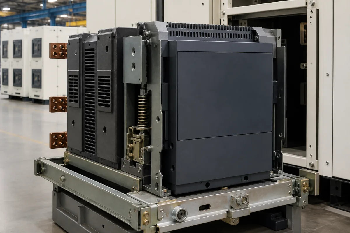
Representative product image. Confirm appearance and specifications with the manufacturer.

Product Specifications

Technical details and manufacturing context for Main Circuit Breaker

Definition
A main circuit breaker is the overcurrent protective and switching device assigned to the incoming or principal circuit of an installation or panel. “Main” describes its system role, not one product construction or standard family. A household or similar AC miniature circuit-breaker can fall within IEC 60898-1, whose scope is limited to AC air-break devices up to 440 V, 125 A and 25 kA. Industrial low-voltage circuit-breakers operated by instructed or skilled persons fall within IEC 60947-2, which uses different ratings, duties and verification. The exact device may use thermal-magnetic or electronic releases and can be MCB, MCCB or another coordinated breaker type. Rated current, voltage, breaking capacity, poles, time-current characteristic, frequency, insulation and impulse ratings, temperature, IP code, endurance, terminal capacity and dimensions are one model’s declared characteristics. The listed ranges are directory comparison prompts and do not form a single guaranteed breaker. Selection requires the earthing/system arrangement, conductor and load, prospective short-circuit current, coordination/selectivity, ambient and grouping derating, enclosure, installation rules and legal manufacturer evidence.
Working Principle
Current passes through the main contacts and a release monitors an overcurrent condition. A thermal element can provide inverse-time overload response, while an electromagnetic or electronic release can respond to high fault current according to the device characteristic. The operating mechanism opens the contacts and the arc-control system interrupts current within the breaker’s verified rating. Some breakers also include residual-current, communication, metering or adjustable protection functions, but these must not be inferred from the category name. Clearing time and safety depend on the actual current waveform, release settings, available fault current, voltage, power factor or time constant, conductor protection, upstream/downstream coordination and installation.
Common Materials
Copper, Thermoset Plastic, Steel
Technical Parameters
ParameterTypical rangeNotes & selection driver
Rated Current63–125 ASelect based on load calculation; higher for larger homes.IEC 60898-1
Rated Voltage230/400 V ACSingle-phase or three-phase supply.IEC 60898-1
Breaking Capacity6–10 kAMust exceed prospective short-circuit current at installation point.IEC 60898-1
Number of Poles1P, 2P, 3P, 4PChoose based on system configuration (single-phase or three-phase).
Tripping CurveB, C, DTime-current characteristic; select from verified load, inrush, conductor protection and installation rules.IEC 60898-1
Rated Frequency50/60 HzCompatible with mains supply.IEC 60898-1
Insulation Voltage500 VMaximum voltage for insulation design.IEC 60898-1
Impulse Withstand Voltage4–6 kVWithstands transient overvoltages.IEC 60898-1
Operating Temperature-25–55 °COutside this range, derating may be required.IEC 60898-1
Degree of ProtectionIP20–IP40Enclosure protection code; confirm whether the rating applies to the breaker, terminal cover, or assembled panel.IEC 60529
Mechanical Endurance10000–20000 operationsNumber of mechanical operations without electrical load.IEC 60898-1
Electrical Endurance4000–8000 operationsNumber of operations under rated current.IEC 60898-1
Connection Cross-Section16–70 mm²Model-specific accepted conductor range; confirm material, class, preparation and terminal data.
Mounting Width36–72 mmFits standard DIN rail; multiple poles increase width.DIN 43880

Ranges are indicative industry figures for RFQ preparation, not a supplier commitment. Confirm every value and standard with the legal manufacturer before ordering.

Components / BOM
  • Trip Unit
    Detects overloads and short circuits to trigger the tripping mechanism
    Material: Thermoset Plastic, Copper Coils
  • Contacts Part
    Conduct electricity when closed and separate to break the circuit when tripped
    Material: Silver Alloy, Copper
  • Operating Mechanism
    Manual lever for ON/OFF control and automatic tripping mechanism
    Material: Steel, Thermoplastic
  • Arc Chute
    Extinguishes the electrical arc formed when contacts separate during interruption
    Material: Deionizing Plates (Steel)

Applied To / Applications

This component is essential for the following industrial systems and equipment:

Industrial Ecosystem & Supply Chain Structure

Complementary Systems
Downstream Applications
Specialized Tooling

Application Fit & Sizing Matrix

Operational Limits
load: Calculate design current, conductor ampacity, inrush/start profile, ambient/grouping derating and duty.
fault: Determine prospective short-circuit current and required breaking/service capacity at the installation point.
system: Record AC/DC system, nominal/maximum voltage, phases/poles, earthing arrangement and installation authority rules.
coordination: Verify selectivity/cascading, backup protection, energy limitation, neutral switching and downstream conductor/equipment protection.
installation: Match terminals, conductor material/class, torque, enclosure/IP boundary, mounting, clearances and service access to one model.
product class: Identify MCB, MCCB, power circuit-breaker, RCBO or other exact class and the applicable product standard.
Sizing Data Required
  • Do not mix IEC 60898-1 Icn with IEC 60947-2 Icu/Ics without model evidence
  • Select rated current and characteristic from conductor and real load/inrush
  • Apply manufacturer ambient, grouping and enclosure derating
  • Verify short-circuit coordination and let-through against protected equipment
  • Require legal manufacturer data, markings and applicable certificate/test report

Reliability & Engineering Risk Analysis

Failure Mode & Root Cause
Breaker cannot safely interrupt the fault
Cause: Prospective short-circuit current, voltage, power factor/time constant or installation condition exceeds the verified rating.
Conductor overheats or nuisance trips occur
Cause: Rated current/curve ignores conductor ampacity, ambient/grouping derating, terminal data or real load/inrush.
Protection coordination fails
Cause: Upstream/downstream time-current and let-through characteristics were not checked for selectivity, backup or equipment withstand.
Maintenance Indicators
  • Discoloration, odor, abnormal terminal temperature or damaged insulation
  • Unexplained operation, inability to reset/close or changed mechanism feel
  • Loose conductor, torque evidence, cracked enclosure or contamination at the declared protection boundary
Engineering Tips
  • Perform documented load and fault-level calculations before selection.
  • Use one model’s declared ratings, terminal instructions and derating tables.
  • Verify coordination with manufacturer curves/tables and inspect/maintain under the installation rules.

Indicative industry ranges for design and RFQ preparation. Confirm the exact figures and applicable standard with the manufacturer before specifying.

Compliance & Manufacturing Standards

Applicable Standards
IEC 60898-1 applies to AC air-break circuit-breakers for household and similar installations at 50/60 Hz, not exceeding 440 V, 125 A and 25 kA. Its citation is conditional on the exact product class and evidence. IEC 60947-2:2024 applies to low-voltage circuit-breakers intended for operation by instructed or skilled persons, generally up to 1 000 V AC or 1 500 V DC. Its ratings and short-circuit terminology must come from the exact model. IEC 60947-1:2020 provides general rules when required by the relevant product standard; it does not establish a universal 16–70 mm² connection range. IEC 60529 classifies protection provided by a stated enclosure. Confirm the rated boundary; IP40 must not be described as dust-protected. DIN 43880 dimensional claims and ANSI C37.13 applicability also require the exact product class and model evidence.

Quoted from the published standard.

Manufacturing Precision
  • No universal ±0.5 mm contact gap, ±10% operating force, 150 °C contact, 5 000 N force, 0.3 pC partial discharge, 2.5 kV/mm dielectric or fixed 125%/10× trip boundary is asserted. Use model declarations and applicable test clauses.
Quality Inspection
  • Verify markings, product class, rated voltage/current/frequency, poles, characteristic and short-circuit rating on one model.
  • Check terminal conductor types/sizes, preparation, torque, temperature rise and enclosure boundary.
  • Confirm dielectric, impulse, trip, endurance and short-circuit evidence under the applicable product standard and declared conditions.

Manufacturers of Main Circuit Breaker

1 company lists this product among what they make. Company figures are quoted from each company's own website; every card states where the relationship came from.

ANEN Power
Shanghai, CN
Listed on the company's own website · profile compiled by CNFX from public sources

Manufacturer listings support early research and capability understanding. They are not certification, ranking, or transaction guarantees.

Technical documentation
Request current drawings, revision history, and a signed specification sheet.
Manufacturing capability
Verify equipment lists, process limits, capacity, and representative production evidence.
Inspection readiness
Confirm test methods, calibrated equipment, sampling plans, and traceable reports.
Supplier transparency
Check the legal entity, factory address, ownership, certifications, and direct contacts.

CNFX does not score or rank suppliers. Buyers must verify all claims and documents with the legal manufacturer before ordering.

Supply Chain Compatible Machinery & Devices

Circuit Breaker Arc Chute

The Circuit Breaker Arc Chute is a critical safety component in electrical circuit breakers, designed to rapidly extinguish electric arcs that form during circuit interruption.

Explore Specs →
Medium Voltage Switchgear Assembly Line

Automated production system for assembling medium voltage electrical switchgear.

Explore Specs →
Motor Terminal Block

A motor terminal block is a standardized electrical component that provides secure, insulated connection points for motor winding leads.

Explore Specs →
PLC Control System

A digital industrial computer control system that monitors inputs, makes decisions based on a custom program, and controls outputs to automate industrial processes.

Explore Specs →

Frequently Asked Questions

Does “main circuit breaker” identify one IEC product class?

No. It identifies the breaker’s role in the installation. Determine whether the actual device is a household/similar MCB under IEC 60898-1, an industrial breaker under IEC 60947-2, an RCBO or another product class before comparing ratings.

Are 63–125 A, 230/400 V and 6–10 kA one guaranteed specification?

No. These are comparison prompts found across possible models. The exact combination, number of poles, rated short-circuit value and conditions must come from one model data sheet and certificate/report.

Can B, C and D curves be selected only by calling a load resistive or inductive?

No. The time-current characteristic must protect the conductor and coordinate with actual starting/inrush current, fault-loop conditions, upstream/downstream devices and applicable installation rules.

Does IP40 mean a dust-protected breaker and does IEC 60947-1 prove 16–70 mm² terminals?

No. IEC 60529 classifies the enclosure boundary stated by the manufacturer; confirm whether it covers the breaker, terminal cover or assembled panel. IEC 60947-1 gives general rules when invoked by a product standard and does not establish one universal conductor range.

Data Basis

Editorial classification, named public sources where available, and source-reviewed manufacturer records.

Preliminary Technical Classification
This page supports structured research, RFQ preparation, and supplier evaluation. It does not replace buyer-led supplier qualification, standards review, or technical approval.
Buyer enquiry

Request manufacturing insight for Main Circuit Breaker

Ask for use case, specification boundaries, supplier type, and RFQ preparation information for this product.

Where it goes
Straight to the CNFX editorial desk, and to the manufacturer if this product is linked to a claimed profile. Nothing is broadcast to a supplier list.
Your details stay here
We do not sell or rent enquiry data, and we do not add you to a mailing list. Used only to answer this request.
No commission, no middleman
CNFX is a directory. We take no cut of any order and never negotiate on a supplier's behalf.
What we don't claim
A listing is not an endorsement. Qualify every supplier and verify every figure yourself before ordering.

Your business information is used only to process this request.

Thank you! Your message has been sent. We'll respond within 1–3 business days.
Sorry, we couldn't send your message. Please try again, or email us at contact@cnfx.com.

Need to Manufacture Main Circuit Breaker?

Compare manufacturer profiles with relevant product and process capability.

Previous Product
Load Sharing Controller
Next Product
Main Power Contactor
Get QuotesChat