Editorial Technical Reference

Power Capacitor Bank

This page explains how Power Capacitor Bank is classified within Electrical Equipment Manufacturing. Technical values and manufacturer relationships are research references; confirm the current specification and supplier evidence for each order.

Technical Definition & Core Assembly

A capacitor bank for industrial power factor correction, storing electrical energy and compensating reactive power.
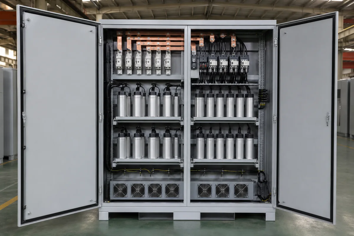
Power Capacitor Bank in a manufacturing environment
Representative product image. Confirm appearance and specifications with the manufacturer.

Product Specifications

Technical details and manufacturing context for Power Capacitor Bank

Definition
A power capacitor bank is a component used in industrial electrical systems to store electrical energy and improve power factor. It consists of multiple capacitors connected in series or parallel configurations, housed in a steel casing with metallized polypropylene film and aluminum electrodes, and often filled with dielectric fluid. The bank is typically part of a larger power factor correction unit, where it counteracts the lagging reactive power drawn by inductive loads such as motors and transformers. By providing reactive power, it brings current and voltage waveforms closer into phase, reducing reactive power consumption, minimizing energy losses, and optimizing distribution efficiency. The bank is available in rated voltages from 400 to 480 V AC, frequencies of 50 to 60 Hz, and reactive power ratings from 5 to 100 kvar, with capacitance tolerance from -5% to +10%. Dielectric loss tangent is ≤0.002, and it can withstand 1.1 times rated voltage for 8 hours per day and 1.3 times rated current continuously. Operating temperature ranges from -25°C to +55°C, with derating above 45°C. Enclosures offer IP54 to IP65 protection, and discharge resistors reduce residual voltage to ≤75 V within 3 minutes. Weight ranges from 50 to 500 kg, and dimensions vary from 600×800×400 mm to 1200×2000×800 mm. These parameters follow IEC 60871-1 and IEC 60529 standards, but actual values must be verified with the manufacturer for specific models. The bank is suitable for indoor or outdoor installation and is used in manufacturing facilities to improve power quality and reduce energy costs.
Working Principle
The power capacitor bank operates by storing electrical charge when voltage is applied across its terminals. In AC systems, capacitors provide reactive power that compensates for the lagging reactive power drawn by inductive loads. By introducing capacitive reactance that opposes inductive reactance, the capacitor bank brings current and voltage waveforms closer into phase, improving the power factor toward unity (1.0). This reduces reactive power flow, lowers line losses, and enhances the efficiency of power distribution.
Common Materials
Metallized polypropylene film, Aluminum electrodes, Dielectric fluid, Steel casing
Technical Parameters
ParameterTypical rangeNotes & selection driver
Rated Voltage400–480 V ACSystem voltage must match capacitor rating.IEC 60871-1
Rated Frequency50–60 HzDerate for higher frequencies.IEC 60871-1
Rated Reactive Power5–100 kvarTotal bank kvar at rated voltage.IEC 60871-1
Capacitance Tolerance-5–+10 %Affects reactive power accuracy.IEC 60871-1
Dielectric Loss Tangent≤0.002Lower loss reduces heating.IEC 60871-1
Maximum Overvoltage1.1 ×Un10% overvoltage for 8h/day.IEC 60871-1
Maximum Overcurrent1.3 ×InContinuous, including harmonics.IEC 60871-1
Operating Temperature-25–+55 °CAmbient, derate above 45°C.IEC 60871-1
Degree of ProtectionIP54–IP65Indoor/outdoor installation.IEC 60529
Discharge Resistor≤75 VResidual voltage within 3 min.IEC 60871-1
Weight50–500 kgDepends on kvar and enclosure.
Dimensions (W×H×D)600×800×400–1200×2000×800 mmFootprint for floor-standing units.

Ranges are indicative industry figures for RFQ preparation, not a supplier commitment. Confirm every value and standard with the legal manufacturer before ordering.

Components / BOM
  • Capacitor Units Part
    Individual capacitors that store electrical energy and provide reactive power compensation
    Material: Metallized polypropylene film with aluminum electrodes
  • Discharge Resistors Part
    Safely discharge stored electrical energy when the capacitor bank is disconnected from power
    Material: Ceramic or wire-wound resistive material
  • Protective Fuses Part
    Isolate faulty capacitor units to prevent damage to the entire bank
    Material: Silver or copper fuse elements
  • Mounting Frame Part
    Structural support and organization of capacitor units within the enclosure
    Material: Galvanized steel
  • Connection Busbars
    Electrical conductors that interconnect capacitor units and provide power connections
    Material: Copper or aluminum

Industrial Ecosystem & Supply Chain Structure

Complementary Systems
Downstream Applications
Specialized Tooling

Application Fit & Sizing Matrix

Operational Limits
pressure: Atmospheric to 1.2 bar (sealed units), N/A for open configurations
other spec: Humidity: 5-95% non-condensing, Altitude: ≤2000m, Vibration: ≤5g, Harmonic Distortion: ≤5% THD
temperature: -40°C to +85°C (operating), -55°C to +105°C (storage)
Media Compatibility
✓ Industrial air (clean/dry environments) ✓ Nitrogen-filled enclosures ✓ SF6 gas insulation systems
Unsuitable: Corrosive/conductive atmospheres (chlorine, ammonia, salt spray) or explosive environments
Sizing Data Required
  • Required reactive power (kVAR)
  • System voltage and frequency (V/Hz)
  • Harmonic spectrum and distortion levels (%)

Reliability & Engineering Risk Analysis

Failure Mode & Root Cause
Dielectric breakdown
Cause: Overvoltage stress, insulation degradation from thermal cycling, moisture ingress, or manufacturing defects leading to internal arcing and short circuits.
Capacitor element swelling/rupture
Cause: Internal pressure buildup from electrolyte decomposition due to excessive harmonic currents, over-temperature operation, or aging, causing case deformation or rupture.
Maintenance Indicators
  • Audible humming, buzzing, or popping sounds from the bank indicating internal arcing or loose connections
  • Visible bulging, oil leakage, or discoloration on capacitor cases signaling internal pressure issues or thermal stress
Engineering Tips
  • Implement regular infrared thermography scans to detect abnormal heating in capacitor elements and connections, allowing proactive replacement before failure
  • Install harmonic filters and maintain voltage within ±10% of rated value to reduce dielectric stress and prevent premature aging from electrical disturbances

Indicative industry ranges for design and RFQ preparation. Confirm the exact figures and applicable standard with the manufacturer before specifying.

Compliance & Manufacturing Standards

Applicable Standards
IEC 60831: Shunt power capacitors of the self-healing type for a.c. systems having a rated voltage up to and including 1000 V ANSI/IEEE 18: Standard for Shunt Power Capacitors EN 60831: Shunt power capacitors of the self-healing type for a.c. systems having a rated voltage up to and including 1000 V

Quoted from the published standard.

Manufacturing Precision
  • Capacitance tolerance: +/-5% of rated value
  • Case dimensions: +/-2mm on length/width/height
Quality Inspection
  • Partial Discharge Test
  • Temperature Rise Test

Manufacturers of Power Capacitor Bank

2 companies list this product among what they make. Company figures are quoted from each company's own website; every card states where the relationship came from.

Shanghai Zhiyou Electric Manufacturing Co., LTD
Shanghai, CN
Listed on the company's own website · profile compiled by CNFX from public sources
Listed there as: “Power Capacitor Bank”
View source page ↗ shanghaipowers.com · checked 2026-09-15
Zhejiang Jiukang Electric Co.,Ltd
Wenzhou, Zhejiang, CN
Listed on the company's own website · profile compiled by CNFX from public sources
Listed there as: “Intelligent Power Capacitor Bank”
View source page ↗ jiukang.com · checked 2026-09-14

Manufacturer listings support early research and capability understanding. They are not certification, ranking, or transaction guarantees.

Share this page
Technical documentation
Request current drawings, revision history, and a signed specification sheet.
Manufacturing capability
Verify equipment lists, process limits, capacity, and representative production evidence.
Inspection readiness
Confirm test methods, calibrated equipment, sampling plans, and traceable reports.
Supplier transparency
Check the legal entity, factory address, ownership, certifications, and direct contacts.

CNFX does not score or rank suppliers. Buyers must verify all claims and documents with the legal manufacturer before ordering.

Supply Chain Compatible Machinery & Devices

Motor Terminal Block

A motor terminal block is a standardized electrical component that provides secure, insulated connection points for motor winding leads.

Explore Specs →
PLC Control System

A digital industrial computer control system that monitors inputs, makes decisions based on a custom program, and controls outputs to automate industrial processes.

Explore Specs →
Control Panel

A centralized interface for monitoring and controlling industrial equipment and processes

Explore Specs →
PLC Control Panel

A centralized interface unit housing the programmable logic controller and associated control components for industrial automation systems.

Explore Specs →

Frequently Asked Questions

What is the typical voltage range for this capacitor bank?

The rated voltage is 400–480 V AC, per IEC 60871-1. Always verify the exact rating for your specific model and application.

How does the capacitor bank improve power factor?

It provides reactive power that offsets the lagging reactive power from inductive loads, bringing current and voltage closer in phase and improving power factor toward unity.

What are the environmental limits for operation?

Operating temperature is -25°C to +55°C, with derating above 45°C. Enclosure protection is IP54 to IP65, suitable for indoor or outdoor installation.

What safety features are included?

Discharge resistors reduce residual voltage to ≤75 V within 3 minutes after de-energization. Overvoltage and overcurrent limits are 1.1×Un and 1.3×In, respectively.

Data Basis

Editorial classification, named public sources where available, and source-reviewed manufacturer records.

Preliminary Technical Classification
This page supports structured research, RFQ preparation, and supplier evaluation. It does not replace buyer-led supplier qualification, standards review, or technical approval.
Buyer enquiry

Request manufacturing insight for Power Capacitor Bank

Ask for use case, specification boundaries, supplier type, and RFQ preparation information for this product.

Where it goes
Straight to the CNFX editorial desk, and to the manufacturer if this product is linked to a claimed profile. Nothing is broadcast to a supplier list.
Your details stay here
We do not sell or rent enquiry data, and we do not add you to a mailing list. Used only to answer this request.
No commission, no middleman
CNFX is a directory. We take no cut of any order and never negotiate on a supplier's behalf.
What we don't claim
A listing is not an endorsement. Qualify every supplier and verify every figure yourself before ordering.

Your business information is used only to process this request.

Thank you! Your message has been sent. We'll respond within 1–3 business days.
Sorry, we couldn't send your message. Please try again, or email us at [email protected].

Need to Manufacture Power Capacitor Bank?

Compare manufacturer profiles with relevant product and process capability.

Previous Product
Wire Tensioning System
Last Product
Get QuotesChat