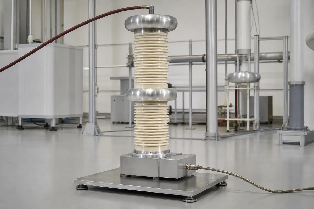
High-voltage measuring dividers for test laboratories and impulse generators · resistive vs damped-capacitive, rated lightning and switching impulse and AC voltage, response time, expanded uncertainty, IEC 60060-1/-2, clearances, toroidal electrodes, secondary unit
A high-voltage measurement divider reduces a test voltage of hundreds or thousands of kilovolts to a level a digitiser or peak voltmeter can record, with a known ratio and fast, faithful response. It stands in high-voltage test laboratories beside impulse generators and AC or DC test sets. Ask three things first: which voltage shapes you must measure — lightning impulse, chopped impulse, switching impulse, AC or DC — since that decides resistive, capacitive or mixed design; the rated voltage and the clearance you have; and the uncertainty and calibration the test standard requires.
High-voltage measuring dividers for laboratory testing — resistive, damped-capacitive and mixed (universal) dividers with secondary units and measuring cables. Low-voltage resistor-divider networks on circuit boards, instrument voltage transformers, voltage sensors for switchgear (see voltage-sensor-potential-transformer) and the impulse generators themselves are outside this page except where compared.
CNFX editorial research · Sources checked October 12, 2026 · 4 sources
Choose resistive or damped-capacitive by the voltage shapes
Haefely, a high-voltage test equipment maker, describes its RT resistive impulse dividers as having very good response parameters, so they are used for full and front-chopped lightning impulses and voltages with steep fronts, and as the choice where extra capacitance in the test circuit is not permissible because it would slow the rise time — which also means they cannot serve as the impulse generator's load capacitor. Their high-voltage resistors are anti-inductively wound CrNi wire, housed in glass-fibre-reinforced epoxy cylinders above 200 kV, with toroidal electrodes above 150 kV for corona-free operation, a coaxial low-inductance secondary unit with LEMO connector, and indoor design. [1] Its CR damped-capacitive dividers are optimised for high dynamic behaviour and measure full and tail-chopped lightning impulses, switching impulses and AC voltages; they can serve as a base load for the impulse generator. Their high-voltage part is one or more oil-filled capacitors in epoxy cylinders with internal damping resistance distributed between capacitor elements and a second damping resistor at the start of the HV lead; toroidal electrodes are fitted above 1,000 kV. [2]
Editorial note: if the laboratory must measure both steep lightning impulses and switching or AC voltages, ask suppliers whether one divider covers all shapes within the required uncertainty or whether separate dividers are needed.
Give the supplier the voltage shapes (LI, chopped LI, SI, AC, DC) and polarities, rated voltage for each, required ratio and output level, uncertainty and calibration (ISO/IEC 17025), response requirements, generator load needs, indoor space and clearances, measuring system and cable length, transport base, and quantity.
02
Check ratings, response time, uncertainty and clearances
Haefely's RT range runs from 50 kV to 3,000 kV rated lightning impulse (1.2/50 µs), with high-voltage resistances of roughly 2.5–15 kΩ and experimental response times under 10 ns for the 200 kV model rising to under 65 ns for 2,000–3,000 kV; heights run from 55 cm to 10.65 m. Expanded uncertainty at 95% coverage over a 10–100% measuring range is ≤3% for full and tail-chopped lightning impulses, ≤5% for front-chopped lightning impulses and ≤10% for time parameters, to IEC 60060-1 and IEC 60060-2 (edition 3, 2010), with ISO/IEC 17025 calibration optional. [1] The CR range runs from 600 kV to 4,000 kV lightning-impulse rating, with negative switching-impulse ratings of 500–3,300 kV (positive switching impulse about 50% of the negative value), continuous AC ratings of 200–1,000 kV RMS with an additional secondary part, capacitances of about 263–1,050 pF, and required clearance to walls and ceiling from 2.5 m to 12 m. [2]
Editorial calculation: with an assumed ratio of 4,000:1, an 800 kV lightning impulse appears as 200 V at the divider output, within the input range of a high-voltage digitiser; a 2,000 kV impulse would give 500 V, so the ratio must be chosen together with the recorder's input range. [1]
03
Check switching-impulse performance and how the response is corrected
In a 2021 peer-reviewed article in IEEE Transactions on Instrumentation and Measurement (vol. 70), Havunen and Hällström of VTT Technical Research Centre of Finland state that the performance of a high-voltage switching impulse (SI) measurement system is highly dependent on the voltage divider used, and that self-built or commercial dividers do not always fulfil the requirements set for reference-level devices. [4]
They describe the VTT MIKES SI measurement systems up to 400 kV: a calculable impulse voltage calibrator is used to calibrate a reference digitizer and a 10 kV divider, and the 10 kV divider then calibrates the 400 kV modular divider. The responses of both dividers are corrected with two different software methods. The largest uncertainty component of time to peak comes from its definition and evaluation under IEC 60060-1:2010 and IEC 61083-2:2013. [4]
Editorial calculation: calibrating the 400 kV divider from the 10 kV divider is a 40:1 step in voltage (400 ÷ 10). Editorial note: if the divider will also measure switching impulses, ask the supplier for the calibration chain behind its SI scale factor, whether any software response correction is applied, and the stated uncertainty of time to peak as well as of peak voltage.
04
Ask for traceable calibration and its uncertainty
FitzPatrick and Kelley of NIST (Journal of Research of NIST, vol. 101, 1996) describe a facility that determines pulse voltage ratios of test dividers from 10 kV to 300 kV by comparison with Kerr electro-optic systems and NIST reference resistive dividers, with relative expanded uncertainties of 0.4% or less (coverage factor k = 2). They note that international standards on high-voltage test techniques require impulse measurement dividers to be traceable to national standards. [3]
The authors explain that impulses are harder to measure than steady voltages because large dividers pick up extraneous signals and suffer stray capacitance, residual inductance and wave-propagation effects that distort fast transients; they state that 0.4% is nearly an order of magnitude below the standards' requirement for ordinary laboratory dividers and more than a factor of two below that for reference systems. [3] Combine this with the maker's response parameters above when judging a divider. [1]
Editorial calculation: on a 1,000 kV lightning impulse, 1% is ±10 kV and 0.4% is ±4 kV.
Measurement (NIST paper)
Relative uncertainty stated
DC divider ratio, 10–100 kV
Below 0.01%
AC divider ratio, 10–100 kV
0.05%
Pulse divider ratio by comparison, 10–300 kV
0.4% or less (k = 2)
Requirement for reference measurement systems in international standards, peak voltage
1%
NIST reference dividers' response time
Of the order of 1 ns (oil-immersed, compact)
Ask for the divider's calibration certificate, the reference it is traceable to, the stated uncertainty and coverage factor for each voltage shape, and the date and interval of recalibration.
05
What to get in writing from a divider supplier
Only the Guodian Huaxing card names a dedicated divider line (HXFRC); the Xinya listing is for coupling capacitors that double as dividers, so check which voltage shapes either one is rated for.
When requesting quotations, ask each supplier for rated voltages per shape, response parameters, uncertainty statements with coverage and range, calibration certificates and clearance drawings.
06
HV arm, damping resistors, electrodes and secondary unit
Damping resistors belong to the CR damped-capacitive design only, and the castored base appears on RT resistive units above 200 kV. [1][2]
Ratio, rated voltage and uncertainty for a divider order
The Haefely datasheets reviewed give no voltage ratio, temperature coefficient or humidity range, so those three values have to come from the supplier.
Divider and coupling-capacitor listings from Xinya and Guodian Huaxing
Jiangsu Xinya High Voltage Testing Equipment Co., Ltd. lists partial-discharge-free coupling capacitors that also serve as voltage dividers; Wuhan Guodian Huaxing Electric Co., Ltd. lists HXFRC voltage dividers.
Jiangsu Xinya High Voltage Testing Equipment Co., Ltd.
Manufacturing site to be confirmed for the order
Its website lists partial-discharge-free coupling capacitors that also serve as voltage dividers.
Explore company information and manufacturing capabilities, then discuss the scope of your project with a relevant supplier.
Share this page
Compiled and source-reviewed by the CNFX editorial team.
Each manufacturer above links to the page on that company's own website where the product is listed, with the date we checked it. How we source and review
· Page last updated 13 October 2026
Buyer questions
When is a resistive divider used?
For steep-fronted and front-chopped lightning impulses, where added capacitance would slow the rise time. [1]
What uncertainty do impulse dividers achieve?
Haefely quotes ≤3% for full and tail-chopped lightning impulses and ≤5% front-chopped, at 95% coverage. [1]
Can one divider measure impulse and AC?
Haefely's damped-capacitive CR dividers measure lightning and switching impulses and, with an extra secondary part, AC voltages. [2]
How accurately can an impulse voltage divider be calibrated?
NIST reported pulse-ratio calibrations from 10 kV to 300 kV with expanded uncertainties of 0.4% or less (k = 2), against a 1% requirement for reference systems in international standards. [3]
How is a switching impulse voltage divider made traceable?
VTT Technical Research Centre of Finland (Havunen and Hällström, 2021) calibrates a reference digitizer and a 10 kV divider with a calculable impulse calibrator, then uses the 10 kV divider to calibrate a 400 kV modular divider, correcting both responses in software. [4]
Sources and what still needs a direct check
Sources checked 2026-10-12. Both datasheets are Haefely documents hosted by its distributor MDL Technologies.