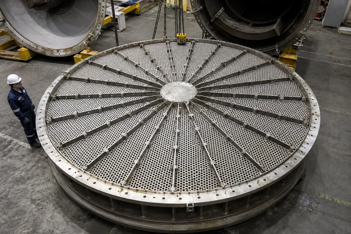
Ammonia synthesis catalyst bed support grid: the perforated floor under an axial-flow converter bed
Converter internals · the flat perforated grid, beams and retention screen under an axial-flow bed of iron synthesis catalyst
In an axial-flow ammonia converter each catalyst bed rests on a floor that has to hold tonnes of iron catalyst at synthesis temperature while letting the converted gas through with little resistance. It is built from perforated plate or grating panels carried on beams, sealed to the basket wall at its rim, and covered by a screen fine enough to keep the granules out of the holes. Three numbers size it: the weight of catalyst above it, how much strength the hole pattern takes out of the plate, and the smallest granule the screen has to stop.
Flat catalyst support grids for the axial-flow and annular axial-flow beds of ammonia synthesis converters: perforated plate or grating panels, radial and cross beams, central hub, rim ring and wall seal, hold-downs and the retention screen laid on the grid. The converter as a whole, its pressure shell, cartridge, inter-bed exchangers, quench system and catalyst choice are covered on the High-pressure ammonia synthesis reactor (ammonia converter) page, and removable catalyst cartridge and basket assemblies on the Reactor core page. Cylindrical collectors and scallops of radial-flow beds, and the gauze support grids of nitric acid ammonia-oxidation burners, are outside this page.
CNFX editorial research · Sources checked October 12, 2026 · 6 sources
Annular, circular and rectangular grids: where the support sits in Kellogg's converter layouts
M. W. Kellogg's European application EP 0 254 936 describes a vertical three-bed converter whose catalyst beds are arranged for axial downward flow, each with an open top surface and a bottom outlet portion contained by perforated supports, which are in turn carried by the inner shell. The upper bed is annular, around a shell-and-tube heat exchanger, so its support is an annular perforated plate; the patent prefers the exchanger's bottom tube sheet to lie in the same plane and names that perforated support as the exchanger's preferred principal support. [1]
Kellogg's granted patent EP 0 256 299 for a horizontal converter divides the inner shell into four adiabatic beds separated by transverse partitions, with gas flowing downward through each bed, and states that the catalyst particles are supported by grids and screens. Here the grid is a rectangle bounded by the inner shell sides rather than a disc. [2]
Both Kellogg documents give the synthesis range as about 70 to 325 bar and about 340 °C to 525 °C, and put the catalyst for a plant at about 40 to 90 m³ in a converter about 2 to 4 m in diameter and 10 to 35 m long. The granted horizontal-converter patent attaches these figures to a 1,000 metric ton per day plant; the vertical-converter application prints 100 metric tons per day for the same figures, so check the plant size behind any reference figure. [2][1] Maxam-Chirchiq's specification for its SA-S iron catalyst gives an operating window of 400 °C to 600 °C at 15 to 55 MPa. [3]
Tell the grid supplier which bed the grid serves, whether it is a full disc, an annulus around an exchanger or a rectangle, and whether anything else (exchanger, downcomer, thermowells) is carried by it.
02
Catalyst at 2.7 ± 0.2 kg/dm³ oxidized and 2.1 ± 0.2 reduced: the weight a grid carries
Iron synthesis catalyst is dense. Maxam-Chirchiq's specification lists a bulk density of 2.7 ± 0.2 kg/dm³ for the oxidized SA-S grade and 2.1 ± 0.2 kg/dm³ for the pre-reduced SA-SV grade. [3] The grid is loaded at its heaviest when oxidized catalyst is charged, before reduction in the converter.
Editorial calculation, with an assumed bed depth of 2.5 m over the whole grid: load per m² = bulk density × 2.5 m; pressure = load × 9.81 m/s²; a 3 m disc (inside the 2–4 m converter diameters in Kellogg's patents) has an area of π × 1.5² ≈ 7.07 m². [3][2] The bed depth and diameter are examples; use the bed drawing.
Editorial note: the grid sits inside the converter's pressure shell, so beyond the catalyst weight it carries the gas pressure drop across the bed and screen in the flow direction, and any weight hung from it such as the exchanger Kellogg supports on the upper-bed plate. [1] Ask the designer for the design load combination, including upset pressure drop.
Give the bed depth, catalyst grade and whether it is charged oxidized or pre-reduced, the design pressure drop across the bed, and any equipment carried by the grid.
03
Hole pattern versus strength: what 40–53 % open perforated plate keeps of the solid plate
The Industrial Perforators Association's handbook gives yield-strength ratios S*/S for round holes in the standard 60° staggered pattern, the strongest arrangement in its tables; the ratio applies to both bending and stretching and is lower in the length direction, parallel to the straight rows of holes. [5]
Editorial calculation: bending strength of a plate scales with yield strength × thickness², so matching a solid plate in the weak direction needs a thickness ratio of √(1/S*/S). For 1/2 in holes on 11/16 in centres that is √(1/0.214) ≈ 2.16, so a perforated panel needs about 2.2 times the thickness of a solid plate for the same strength; for 3/8 in on 1/2 in it is √(1/0.192) ≈ 2.28. [5] This is why the perforated panels are kept to short spans between beams rather than spanning the bed.
Editorial calculation: holes of 9.5 mm or 12.7 mm are larger than the 5–7 mm and 7–10 mm granule fractions in Maxam-Chirchiq's catalyst specification, so a plate with these holes only works with a screen on top. [5][3] Kellogg's horizontal converter likewise names grids and screens together. [2]
Ask for hole diameter, pitch and pattern orientation relative to the beams, plate thickness, span between beams, and the strength calculation at design temperature.
04
Retention screen opening against 1.5–3 mm, 6–10 mm and 5–15 mm granule fractions
The screen on the grid is sized by the smallest catalyst particle that rests on it. Clariant offers AmoMax 10 Plus as irregular granules with rounded ends in 1.5–3 mm, 6–10 mm and 8–12 mm sizes. [4] Maxam-Chirchiq supplies SA-S and SA-SV in 5–7, 7–10 and 10–15 mm fractions, with at least 78 % in the normalized fraction and no more than 3 % at or below 0.5 mm. [3]
Editorial note: when a bed is graded, with a coarse layer over the grid and finer catalyst above, the screen is set by the layer in contact with it. Where a converter is charged with a finer grade than the original design, check the existing screen opening against the new lower size bound before loading. [4][3]
Opening below 5 mm; fines below 0.5 mm can pass any practical coarse screen.
State the catalyst size fraction resting on the grid, the screen type and opening, how screen sheets are joined and how the screen edge is closed against the wall.
05
Rim seal and hold-downs: keeping catalyst from bypassing the grid edge
A grid that is strong enough can still leak at its edge. Johnson Screens' case note describes molecular-sieve dehydrators in which a mesh-and-grating assembly leaked sieve, had to be patched during shutdowns and was hard to seal at the edges of the mesh panels; its replacement grid was installed with J-bolts to prevent uplift of the bed support during operation and with rope packing between the vessel wall and the grid outside diameter to prevent bypass. [6]
The same note records that the original grids on that site had run for over twenty years without repairs, and that a later annulus seal design gives greater thermal growth allowance. [6] The service is gas dehydration, not ammonia synthesis, but the two failure paths it names, uplift and leakage at the wall, are the ones to check on a converter grid that heats from ambient to the 340–525 °C range in Kellogg's patents. [1]
The pictured grid shows the elements involved: perforated panels with staggered round holes, radial bars clamped along the panel joints, a solid central hub plate and a bolted rim ring on a deep stiffened skirt.
Ask how the rim is sealed to the basket wall, how radial growth between grid and shell is accommodated, and what holds the grid down against reverse pressure drop.
06
Data to send for a converter catalyst support grid
Paste it into your enquiry below or into an email to a maker, then replace every bracket.
Converter: [vertical or horizontal; bed number; axial or annular bed]
Grid shape: [disc diameter; annulus inside and outside diameter; rectangle size]
Load: [bed depth; catalyst grade; oxidized or pre-reduced charge; design pressure drop; equipment carried]
Temperature: [design temperature at the grid; start-up and upset cases]
Plate: [hole size; pitch; pattern; thickness; open area]
Beams: [layout; span; hub]
Screen: [catalyst fraction on grid; opening; joining; edge closure]
Seal and fixing: [rim seal; thermal growth; hold-downs]
Installation: [manway size; segment size and weight]
Documents: [drawings; strength calculation; material certificates]
Explore company information and manufacturing capabilities, then discuss the scope of your project with a relevant supplier.
Share this page
Compiled and source-reviewed by the CNFX editorial team.
Each manufacturer above links to the page on that company's own website where the product is listed, with the date we checked it. How we source and review
· Page last updated 13 October 2026
Buyer questions
How much does the catalyst on a support grid weigh?
With Maxam-Chirchiq's bulk density of 2.7 ± 0.2 kg/dm³ for oxidized catalyst, a 2.5 m deep bed puts about 6.75 t on each square metre, about 48 t on a 3 m disc (editorial calculation). [3]
Why does a perforated grid need a screen?
Plate holes of 9.5–12.7 mm keep strength and open area, but they are larger than 5–10 mm catalyst granules; Kellogg's horizontal converter supports catalyst by grids and screens. [5][3][2]
How much strength does perforation remove?
In IPA's tables, 1/2 in holes on 11/16 in centres (47 % open) keep 0.273 of the solid yield strength across the stagger and 0.214 along the rows. [5]
Sources and what still needs a direct check
Sources checked 2026-10-12. Kellogg's patents describe where grids sit in its converters; Maxam-Chirchiq and Clariant give catalyst sizes and density; the Industrial Perforators Association gives perforated-plate strength ratios; Johnson Screens' note concerns a dehydrator grid seal.