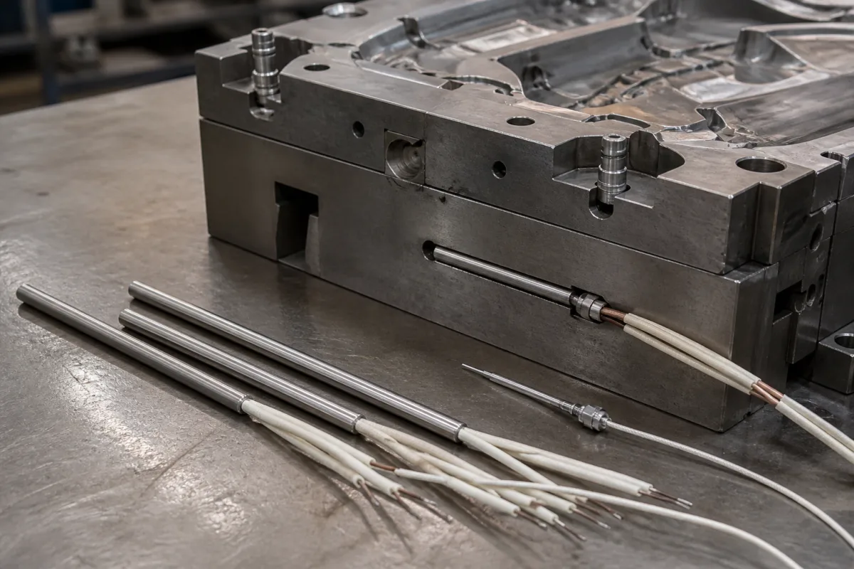
Casting mould temperature control cartridge heater
Cartridge heaters for mould and die heating · Diameter, length and wattage tolerances, watt density against hole fit and part temperature, sheath material and temperature limits, voltage and current per diameter, camber, lead seals and terminations
A cartridge heater is a tubular electric heating element — resistance wire packed in compacted magnesium oxide inside a metal sheath — that slides into a drilled hole in a mould, die or platen and heats it by conduction, with a thermocouple and controller holding the set temperature. Ask three things first: what diameter, heated length and hole fit the mould allows, what watt density the part temperature and fit permit, and what voltage, current, leads and seals the installation needs.
Swaged and similar cartridge (insertion) heaters for heating moulds, dies, platens and tooling in casting, moulding and packaging, with built-in or separate thermocouples. Band heaters (see heater bands), cast-in heaters, hot-runner coil heaters, induction heating and mould temperature control units using water or oil are outside this page except where compared.
CNFX editorial research · Sources checked October 12, 2026 · 4 sources
Fit the heater to the hole and the part temperature
Watlow's FIREROD cartridge heater data sheet describes nickel-chromium resistance wire, conductor pins and magnesium oxide insulation in an Alloy 800 sheath, rated for part temperatures up to 760 °C (1,400 °F), watt densities up to 62 W/cm² (400 W/in²) and up to 480 V, with mould, die and platen heating among its applications. Diameter tolerance is ±0.05 mm (±0.08 mm for 25 mm units); sheath length tolerance ±2.4 mm up to 114 mm, then ±2% (±3% for 1/8 in units); actual diameters run 3.1 mm (1/8 in) to 25.3 mm (1 in) with maximum lengths of 305–1,830 mm. [1]
Its maximum-watt-density chart for heating metals relates hole fit, watt density and application temperature. Hole fit is the maximum hole diameter minus the minimum heater diameter: a 0.500 in (13 mm) hole and a 0.496 in ±0.002 in (12.6 mm) heater give 0.006 in (0.15 mm). The chart is for steel parts; for stainless steel enter it with a fit 0.04 mm larger than actual, and for aluminium and brass with a temperature 38 °C above actual. For square holes or grooves the maker asks to be contacted. Camber is limited to 0.020 in × (length in feet)² or 0.005 in, whichever is greater. [1]
Tempco defines fit for its Hi-Density cartridge heaters as the difference between the heater's minimum diameter and the hole's maximum diameter: a 3/8 in heater (actual 0.371 ± 0.002 in) in a 0.376 ± 0.002 in hole has a fit of 0.009 in. It notes that for medium watt densities below 60 W/in² and temperatures below 600 °F (315 °C) holes are drilled, with holes running 0.003–0.008 in over drill size, while higher watt densities or temperatures call for drilled and reamed holes; tighter fit allows higher watt density and longer life, while looser fit eases installation and removal of long heaters, and heaters can be centreless ground to ±0.0005 in. [3]
Tempco rates its Hi-Density heaters for sheath temperatures up to 1,400 °F (760 °C) but warns that lead wires and terminations are rated much lower, so long heaters can carry an unheated section to bring the lead end out of the hot zone; it also advises reamed holes, drilling through the part where possible to ease removal, and an anti-seize coating. [3]
Editorial calculation: a 12.6 mm (0.496 in) heater with an assumed 100 mm (3.94 in) heated length has a heated surface of about π × 0.496 × 3.94 ≈ 6.1 in²; at 400 W that is about 65 W/in² (10 W/cm²). Read the allowed watt density for your part temperature and hole fit from the maker's chart, and reduce wattage or improve the fit if the design exceeds it. [1]
Give the supplier the mould material, hole diameter and tolerance (and whether through or blind), heater diameter and overall and heated length, required wattage and voltage, part operating temperature, thermocouple type and position, lead length and protection (braid, conduit), seal type against oil, moisture or plastic, termination, mounting (flange, fitting) and quantities.
02
Set electrical data, leads and seals
The data sheet gives wattage tolerance of +5%/−10% (+10%/−15% for 1/8 in units) and resistance tolerance of +10%/−5%, with room-temperature resistance before use about 90% of the Ohm's-law value and about 95% after use. Maximum ratings per diameter run from 240 V and 3.1 A at 1/8 in to 480 V and 23 A at 5/8–1 in, with 3/4 and 1 in units available with three (3/4 in) or five (1 in) single-phase circuits, or one or two three-phase circuits. Component recognitions are listed to 240 V AC (UL, CSA, VDE). [1]
Standard lead insulation is rated to 250 °C; made-to-order silicone rubber seals and leads protect against moisture, lubricating oil, cleaning solvents, plastic and fumes up to 150 °C continuous, and epoxy seals up to 121 °C. In 21 °C still air a pre-oxidised heater reaches about 784 °C sheath temperature at 6.8 W/cm² (44 W/in²), where the maker expects about one year of life if cycling is not too frequent, and higher temperatures shorten life. [1]
Tempco's standard specifications run from 1/4 in (6.25 mm actual) to 1 in (25.30 mm) diameter, with maximum voltage of 240 V up to 1/2 in and 480 V from 5/8 in, maximum current of 4.4 A to 23 A, maximum wattage at 240 V from 1,050 W to 5,520 W (11,000 W at 480 V on the larger sizes), lengths from 1 in to 36–72 in by diameter, wattage tolerance of +5%/−10% and resistance tolerance of +10%/−5%; current ratings assume ambient up to 250 °C with mica-insulated leads, and cold resistance is set 3.3% below hot resistance. Camber tolerance is 0.005 in up to 6 in long and 0.020 in per foot beyond. [2]
Editorial calculation: a 1/2 in Tempco heater at its 2,520 W maximum on 240 V draws 10.5 A (2,520 ÷ 240), equal to its listed maximum current for that diameter. [2]
Editorial note: on casting moulds, protect leads and seals from molten metal splash, release agent and cooling water, and ask how the heater is removed if it seizes in the hole.
03
Compare a split-sheath heater for oversized or worn bores
Dalton Electric's Watt-Flex cartridge heaters use a split sheath whose two halves expand against the bore at operating temperature and contract on cool-down for removal, so the maker says they do not rely on a tight installation fit. Its stated guideline is a bore about 0.007 in (0.18 mm, editorial conversion) larger than the nominal heater diameter, with diameter tolerances of ±0.002 in for 1/4–3/4 in, ±0.0025 in for 1 in, ±0.05 mm for 8–20 mm and ±0.06 mm for 25 mm, and length tolerance of ±3% (3/32 in minimum), ±2% above 20 in (500 mm). [4]
The same page lists lead options: Teflon tape with glass braid (TGGT) and extruded PFA leads rated to 480 °F (250 °C), and fibreglass high-temperature leads rated to 840 °F (450 °C); rubber sleeving is offered below 450 °F (230 °C). Its wattage method adds heat-up watts, (weight in lb × specific heat × temperature rise in °F) ÷ (3.412 × heat-up hours), to heat-loss watts and multiplies the sum by 1.2 as a 20% safety factor. [4]
Editorial calculation: Dalton's maximum watt densities of 225 W/in² (1/4 in) to 75 W/in² (1 in) equal about 34.9 to 11.6 W/cm² (÷ 6.4516). These are catalogue ceilings by diameter; the allowed value at your part temperature and fit still comes from the chart of the heater actually quoted. [4][1]
Fill the specification fields with values for your mould
A cartridge heater quotation needs values for your mould. The table explains each field, gives published values where a reviewed source states them, and says what to obtain from the supplier.
Field
What it means and published values
Ask the supplier for
Diameter
3.1–25.3 mm actual; ±0.05 mm. [1] E.g. 1/4–1 in (6.25–25.30 mm). [2]
Actual diameter and tolerance.
Hole fit
0.15 mm in the maker's example. [1] E.g. 0.009 in example. [3]
The manufacturers below list cartridge heaters for mould and die heating on their own websites; each card links to the page reviewed. Confirm ratings, materials and approvals for your order.
Jiangsu Sinton Group
Manufacturing site to be confirmed for the order
Lists cartridge heaters with applications including injection blow moulding, hot runner bushings, hot plates and moulds and dies.
Explore company information and manufacturing capabilities, then discuss the scope of your project with a relevant supplier.
Share this page
Compiled and source-reviewed by the CNFX editorial team.
Published product pages show what a company offers, not tested performance. Confirm the legal seller, factory, approvals and scope for your order. How we source and review
· Page last updated 13 October 2026
Buyer questions
How do I calculate cartridge heater hole fit?
Subtract the minimum heater diameter (nominal minus tolerance) from the maximum hole diameter; the maker's example gives 0.15 mm. [1]
What watt density can a cartridge heater run at?
Up to 62 W/cm² in one range, but the allowed value falls as part temperature and hole fit increase; read it from the maker's chart. [1]
Why does a cartridge heater burn out early?
High sheath temperature shortens life; in still air one heater reaches about 784 °C at 6.8 W/cm² with about one year of expected life. [1]
How tight should a cartridge heater fit in its hole?
Fit is the heater's minimum diameter against the hole's maximum; one maker's example is 0.009 in, with reamed holes recommended for high watt density or temperature. [3]
Does a split-sheath cartridge heater need a reamed tight-fit hole?
Dalton says its Watt-Flex split-sheath heaters do not rely on a tight installation fit and recommends a bore about 0.007 in larger than the nominal diameter; the sheath halves expand against the bore when hot. [4]
Sources and what still needs a direct check
Sources checked 2026-10-12. Watlow's and Tempco's data sheets describe their own solid-sheath cartridge heaters, and Dalton Electric's technical page describes its split-sheath Watt-Flex range; they are used here to show what a specification covers. Ratings for your mould must come from the supplier's data for the heater offered.