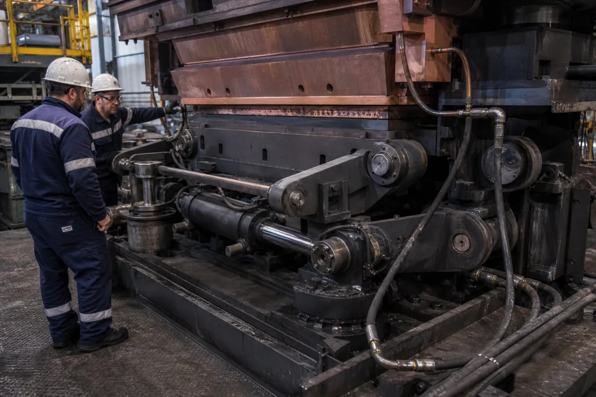
Continuous casting mould oscillation mechanism: the eccentric, lever and leaf-spring guidance that moves the mould along the casting arc
The mechanical guidance under a caster mould · how eccentrics, levers and leaf springs make the mould follow the casting arc, where play and wear come from, and the bearing-free designs that replace pins and bushings
A continuous casting mould has to move up and down a few millimetres, hundreds of times a minute, to stop the solidifying shell sticking to the copper. On a curved caster that motion is not straight: the mould must swing along the arc of the strand, so the outer-radius face travels slightly further than the inner one. Whatever produces the stroke — eccentric shafts, a crank and lever linkage, or hydraulic cylinders — something has to guide the mould so it moves only along that path, without sideways play or rocking. This page is about that guiding mechanism: how it makes the arc, where its play comes from, and how bearing-free spring guidance replaced pins and bushings.
Mechanical oscillation and guidance mechanisms for continuous casting moulds — four-eccentric and lever-linkage oscillators, guide rods, check rods, leaf-spring and elastic-bar guides, anti-roll bars and exchangeable oscillation frames — for slab, bloom and billet casters, straight or curved. Oscillation tables as complete units, hydraulic drives, waveform, stroke and frequency settings and their control are covered on the Heavy-duty continuous casting mold oscillator page; strand guide segments below the mould on the Strand guide system for continuous casters page; mould copper plates on the Continuous casting mold copper plate page; mould flux on the Continuous casting mould flux (mould powder) page. Complete casters are outside this page.
CNFX editorial research · Sources checked October 12, 2026 · 5 sources
Following the casting arc: a larger throw on the outer radius than the inner
Herbert Lemper's US patent 4,953,614 describes a mould oscillator for a curved slab caster carried on two shafts with two offset eccentrics each, one under each corner of the mould table, driven together by one motor through right-angle gear reducers. The eccentrics near the outside-radius mould plate are offset further from their shaft axes than those near the inside-radius plate, so they have a larger throw; this lets the mould rotate slightly as it oscillates and follow its curved casting path. [1]
SMS's EP0032116 describes the same principle in an earlier eccentric drive: on curved casters, cam discs of different eccentricity are used, the inner-radius discs having a smaller eccentricity than the outer ones. [2] Danieli's EP1996351 reaches the arc without eccentrics of different size: part of its elastic guiding bars can be installed inclined to the horizontal about a shared axis of rotation, so the table oscillates along a circular arc of a chosen radius, matching a curved mould. [5]
Editorial calculation: on a circular path the stroke at each face scales with its distance from the arc centre. Assuming a caster radius of 10 m at the inner face and a mould 254 mm thick — the 10-inch slab Lemper gives as an example — a 4 mm stroke at the inner face corresponds to 4 × 10.254 ÷ 10 ≈ 4.10 mm at the outer face. The 10 m radius is an assumption for illustration, not a value from the sources.
Editorial note: give the supplier the caster radius at the mould, the mould thickness between inner and outer faces, and the stroke range; ask how the mechanism makes the outer face travel further and how far the motion departs from the true arc across the stroke range.
02
Where play comes from: pins, spherical bushings and guide rollers that barely turn
Lemper explains why conventional linkages wear: eccentrics drive separate links connected to the mould table through spherical bushings or bearings, and the extremely small rotation of these bushings causes lubrication failure in the loading zone, leading to rapid wear and excessive clearance. His design replaces them with solid links of standard wide-flange beams welded to the mould table, flexible enough horizontally to let the eccentric shafts turn, and locates the table horizontally and in the casting direction with adjustable check rods instead of guide rollers. [1]
SMS's EP0032116 makes the same complaint about guide rollers on a lifting table: rollers that make only the smallest swivelling movements suffer high wear, which disturbs running accuracy and smoothness. [2] Danieli's EP1791664, for bloom and billet tables, notes that lever oscillators hinged at both ends need bearings and other wearing parts with costly maintenance, and that bearing backlash causes unwanted table movements that increase at higher oscillation frequencies. [4]
Early leaf-spring guidance had its own faults. Danieli summarises a design with two stacked leaf-spring assemblies that had to carry all guide forces, so the springs were made much longer and thicker than tension alone required; that needed larger drive forces, shortened spring life under alternating bending, and gave larger deflections and deviations from the guide path, with thermal effects more noticeable. [4]
03
Bars and springs instead of bearings: lighter tables that keep their guidance
The later designs guide the mould only with elastic members that bend in the oscillation direction and resist movement in every other. Danieli's EP1791664 uses plain bars rather than multi-leaf springs, states that this improves guidance precision and reduces oscillation marks — more so at higher frequencies — that the bars compensate thermal expansion automatically, and adds an anti-roll device of two or more pairs of bars, half in tension and half in compression depending on the torsional moment. Its drive transmits motion through a rod working in bending, so the drive too has no mechanical bearings. [4]
Danieli also states that its design allows longer strokes than tables with large springs clamped at both ends, and that with no bearings, pins, joints or runners there is no clearance to grow with wear at high oscillation frequencies. [5]
SMS's EP2276593 addresses maintenance rather than motion: the mould sits on leaf-spring guide elements on both sides of the strand axis which, with their bearing blocks, form an exchangeable oscillation unit on a base plate laid directly on the foundation, while the hydraulic oscillation drives sit below the base plate in a recess in the foundation. Because the mould support plate and guide elements wear and need changing at shorter intervals than the drive, the two can be removed separately, and changing the drive does not require lifting the guide unit. [3]
Lemper gives the operating figures of his oscillator: a vertical stroke of about 4 mm at the back-face (inner-radius) mould plate was found satisfactory, with a slightly larger stroke at the outer face; a 50-horsepower DC motor and an oscillation frequency of 20–400 strokes per minute gave good results; and placing one eccentric under each corner of the table removes oscillation inaccuracies at small strokes and high frequencies. [1]
Editorial calculation: at 400 strokes per minute one cycle takes 0.15 s; a 4 mm stroke covered down and up in each cycle means 8 mm × 400 ÷ 60 ≈ 53 mm/s average mould speed, and 20 strokes per minute gives about 2.7 mm/s. How the stroke and frequency are chosen against casting speed is a process setting covered on the oscillator page named above; the mechanism has to deliver it without play over that whole range.
05
What to give a supplier of an oscillation mechanism
Paste it into your enquiry below or into an email to a maker, then replace every bracket.
Caster: [slab, bloom or billet; straight or curved; radius at the mould]
Mould: [thickness between faces; width; mass with water]
Motion: [stroke range; frequency range; waveform; drive type]
Guidance: [eccentric, lever, leaf-spring or elastic-bar; anti-roll; lateral and longitudinal stiffness]
Maintenance: [wearing parts; exchange of guide unit and drive; lubrication]
Acceptance: [measured stroke at inner and outer faces; lateral deviation over the stroke]
Explore company information and manufacturing capabilities, then discuss the scope of your project with a relevant supplier.
Share this page
Compiled and source-reviewed by the CNFX editorial team.
Each manufacturer above links to the page on that company's own website where the product is listed, with the date we checked it. How we source and review
· Page last updated 13 October 2026
Buyer questions
How does a mould oscillator follow the arc of a curved caster?
By giving the outer-radius side a larger throw than the inner: Lemper uses eccentrics with a larger offset on the outer side, SMS cams of larger eccentricity, and Danieli inclined elastic guide bars. [1][2][5]
Why do oscillation linkages wear?
Lemper says spherical bushings that turn only slightly lose lubrication and wear quickly, and Danieli says bearing backlash causes unwanted movements that grow at higher frequencies. [1][4]
How much lighter is a spring-guided thick-slab table?
Danieli's EP1996351 cites 10 tonnes for its first embodiment against 40 tonnes for a conventional table, and 10–20 tonnes overall. [5]
What stroke and frequency does an eccentric oscillator run at?
Lemper's four-eccentric design used about 4 mm stroke at the inner face and 20–400 strokes per minute from a 50 hp DC motor. [1]
Sources and what still needs a direct check
Sources checked 2026-10-12. The four-eccentric oscillator, its arc-following throw and operating figures come from Herbert Lemper's US patent 4,953,614 (read from the USPTO scan); eccentric cams of different eccentricity and leaf-spring suspension from SMS's EP0032116; the exchangeable leaf-spring oscillation unit from SMS's EP2276593; elastic-bar guidance, anti-roll bars and table weights from Danieli's EP1791664 and EP1996351. Patents describe what their applicants claimed, not measured plant performance.