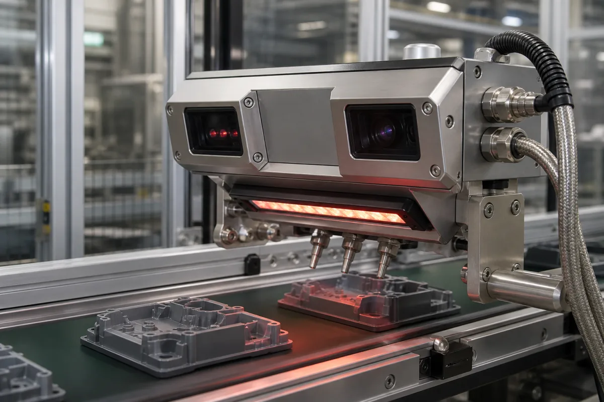
Detection sensor head for sensor-based sorting: the camera, NIR or induction sensing unit and its lighting that spots foreign material or defects on a chute or belt and times the air jets that eject it
The sensing end of a sorter that finds foreign material and blows it out · line-scan colour cameras, NIR hyperspectral sensors and induction sensors over a chute or belt, their illumination, resolution and scan rate, and the delay to the air-nozzle bar
Optical and sensor-based sorters remove stones, foreign grains, plastics, metal or defective pieces from a stream of product without stopping it. The machine is a feeder, a chute or belt, a row of compressed-air nozzles, and above or beside the stream a detection head: one or more line-scan cameras or spectral sensors with their illumination, and sometimes an induction sensor for metal. Everything the machine can find is set by that head — which wavelengths it sees, how many pixels it spreads across the working width, how many lines a second it reads — and by how accurately its decision is timed to the valve that fires when the piece reaches the nozzles.
Detection heads of sensor-based and optical sorting machines: colour (VIS) line-scan cameras, NIR hyperspectral and multispectral sensors, induction sensors, front, back and through-belt illumination, spatial and spectral resolution, scan rate, working width, and the delay and blow-out settings that link the head to the air-nozzle bar. Balanced-coil metal detector search heads on food lines are covered on the Metal detector search head and aperture page and complete food metal detectors on the Food-line metal detector page; laser line profile scanners on the Laser scanner modules page; fast reject and air-jet valves on the Control solenoid valve page; general-purpose line scan cameras on the Line scan camera page; X-ray inspection shielding on the Radiation shielding housing for food X-ray inspection machines page.
CNFX editorial research · Sources checked October 13, 2026 · 4 sources
What the head sees: 4,096-pixel colour line scan at 14 kHz against a 312-pixel NIR sensor at 500 Hz across the same 0.5 m chute
The experimental sorter of the Chair for Waste Processing Technology and Waste Management (AVAW), a CLARITY MONTANUNI-01 machine built by Binder+Co, carries three sensors over a 0.5 m glass chute for pieces from 5 to 300 mm: an EVK Helios NIR G2-320 hyperspectral sensor, an e2v AViiVA SC2 colour line-scan camera, and a Pulsotronic MESEP FS3 induction sensor for electrical conductors. Their published specifications show how differently two heads on one machine resolve the stream. [1]
Editorial calculation, with an example stream speed: across the 0.5 m chute the colour camera's 4,096 pixels each cover about 500 / 4,096 ≈ 0.12 mm, the NIR sensor's 312 pixels about 1.6 mm. Along the stream, at an example speed of 2 m/s, 14,000 lines a second give one line every 0.14 mm, 500 frames a second one every 4 mm. [1] The companion study describes the NIR sensor as determining molecular composition, the colour camera as sorting by visible colour and the induction sensor as finding metallic particles. [2]
A companion study comparing three sorters lists other NIR heads: a Photonfocus MV3-D640I-CL (InGaAs with CMOS read-out, 649 × 512 pixels, 15 × 15 µm, 930–1,700 nm) on a 0.4 m chute machine, and an Inno-Spec RedEye 1.7 (InGaAs, 320 × 256 pixels, 30 × 30 µm, 950–1,700 nm, 9 nm) on a belt sorter 1.2 m wide, split to 0.6 m for the trials. [2]
In food, a legume sorter studied for gluten-free production uses five independent channels; in a free-fall zone of about 10 cm on the chute the product is read by two InGaAs NIR cameras at up to 15,000 Hz and 0.06 mm (60 µm) optical resolution and by two 4,096-pixel RGB cameras viewing front and back, before solenoid-valve air jets reject what the classifier flags. Wavelengths chosen in laboratory hyperspectral work (1,000–1,700 nm on a 320 × 256 InGaAs camera, 5 nm steps) were run on the machine in a 15 nm broadband mode, and the authors report 100 % correct classification of the contaminants by their classifier, while also noting that the parameters used do not allow total separation because the contaminants are not homogeneous. [3]
Detects electrical conductors such as metal, including metallised foils, which are difficult for NIR to detect [1]
Name the contaminants to be found and the product they hide in, the working width, product speed or throughput, and ask which sensor (VIS, NIR, induction) sees each contaminant, with its spectral range, pixels across the width and line rate.
02
Lighting the stream: front and back cameras, halogen for SWIR, and pulsed LED backlight through the belt
A detection head is only as good as the light it gets. Key Technology now offers its COMPASS belt-fed sorter with pulsed LED backlight in visible and near-infrared wavelengths that shines through the belt rather than lighting the product only from above; Key says this improves product segmentation, reduces shadows and limits the effect of belt staining on defect and foreign-material detection, citing kettle chips as a case. [4]
The same announcement adds an optional second ejection manifold for three-way sorting — product, rework and reject, or two grades — in one pass, and a B200 model with a 2 m wide belt. [4] In the legume study, the cameras view the falling product from front and back, and the laboratory SWIR camera was lit by a 150 W halogen source emitting from 800 to 2,000 nm. [3]
Editorial note: a backlight, a second camera on the far side of a chute and a second ejection manifold all add to the head's view or decisions without changing its sensor; ask which of these a quoted machine has.
State whether the product is on a belt or in free fall, whether both faces must be inspected, and whether backlighting, multiple wavelengths or a second ejection stream are needed.
03
From detection to air blast: a 65 ms delay, 15 ms minimum blow-out and 3 mm minimum object in one induction trial
The head's decision is only useful if a valve fires when the piece reaches the nozzle bar. On the AVAW machine, the operator sets the delay time from detection to valve activation, the minimum blow-out time, the minimum object width (1 to 100 mm), and the valve activity — how far an object must reach into a valve's path before that valve fires (10 to 100 %). The delay accounts for the distance from the detection area to the nozzles and for how the material falls. [1]
The authors note that the reaction time can be changed for the material's aerodynamics: metallised foils drop slowly, so the reaction time could be increased, whereas sensitivity and reaction time had to be decreased when removing metal from refuse-derived fuel. Air pressure that is too low for a dense object fails to push it over the splitter. [1] The companion study adds that dense metal pieces need different delay and discharge-pressure settings from lighter plastics in the same stream. [2]
Editorial calculation, with an example speed: at 2 m/s a 65 ms delay corresponds to the piece travelling 0.13 m between detection and nozzle, and a 15 ms blow-out to 30 mm of travel — wider than the 3 mm minimum object, so a pulse covers a small piece completely. [1]
Induction sorting trial setting (Friedrich et al. 2022)
Ask for the distance from the detection line to the nozzle bar, the nozzle pitch, the delay and minimum blow-out time the controller allows, and how the settings are adjusted for different product densities.
04
Detection head details to send
Paste it into your enquiry below or into an email to a maker, then replace every bracket.
Product: [material; piece size range; throughput]
Contaminants: [foreign material and defects to find]
Sensors: [VIS colour; NIR range; induction]
Resolution: [pixels across working width; line rate; spectral resolution]
Lighting: [front, back, through-belt; wavelengths]
Geometry: [chute or belt; working width; detection-to-nozzle distance]
Ejection: [delay; blow-out time; minimum object; streams]
Explore company information and manufacturing capabilities, then discuss the scope of your project with a relevant supplier.
Share this page
Compiled and source-reviewed by the CNFX editorial team.
Each manufacturer above links to the page on that company's own website where the product is listed, with the date we checked it. How we source and review
· Page last updated 13 October 2026
Buyer questions
What resolution does a sorter detection head have?
In published setups, a colour line scan camera with 4,096 pixels at up to 14 kHz and an NIR sensor with 312 pixels at 500 Hz across a 0.5 m chute; an industrial legume sorter used NIR cameras with 0.06 mm optical resolution. [1][3]
What wavelengths do NIR sorting sensors use?
The NIR heads listed in two sorting studies cover 930–1,700 nm or 950–1,700 nm with about 9 nm spectral resolution. [1][2]
How is the air jet timed to the detection?
The controller applies a delay from detection to valve activation and a minimum blow-out time; one induction sorting trial used 65 ms and 15 ms with a 3 mm minimum object. [1]
Why use a backlight in an optical sorter?
Key Technology says its pulsed visible and NIR LED backlight, shining through the belt, improves segmentation and reduces shadows and the effect of belt staining. [4]
Sources and what still needs a direct check
Sources checked 2026-10-13. Four sources from three publishers: two open-access sensor-based sorting papers by Friedrich and colleagues (MethodsX 2022 and Polymers 2023), a 2024 Foods paper on an industrial hyperspectral sorter for legumes, and Key Technology's announcement of COMPASS sorter enhancements.