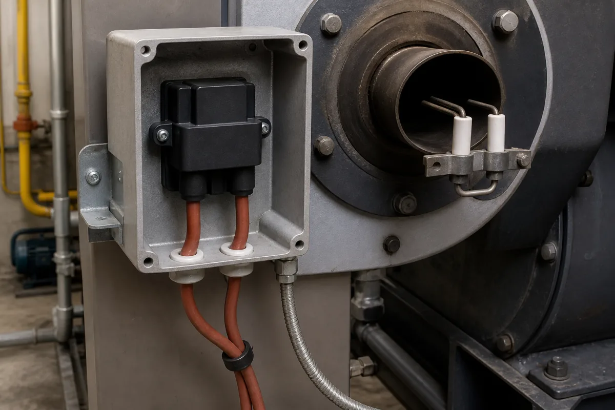
Ignition system for an oil or gas burner (the ignition unit, high-voltage leads and electrodes that light the flame)
The spark ignition of an oil or gas burner · electronic ignition unit with 2 × 7.5 kV or 12 kV output, intermittent or constant duty, 2.5 to 5 mm between electrodes, no divergent electrodes, and where the electrode tips sit relative to the oil nozzle
A burner's ignition system turns mains voltage into a high-voltage spark between two electrodes, or between one electrode and the burner frame at the burner head. Two choices decide whether it lights reliably: an ignition unit with the right output and duty for the burner's start sequence, and electrodes set to the gap and position the burner maker gives.
Spark ignition for oil and gas burners: electronic ignition units, high-voltage leads and ignition electrodes. Complete burners are covered on the Industrial burner page; start-up timings and burner safety sequences on the Industrial furnace combustion system with air preheat and burner safety sequence page; oil nozzles on the Fuel nozzle for oil burners (pressure-atomising) page; flame detection on the Flame sensor and scanner page; engine ignition coils on the Ignition coils (engine ignition transformers) page.
CNFX editorial research · Sources checked October 13, 2026 · 3 sources
Ignition unit: output, current and how long it may spark
Danfoss's EBI4 series offers 2-pole units with the secondary midpoint grounded (2 × 7.5 kV) and 1-pole units for "ignition between one electrode and frame" (12 kV). The HP series is described as a "very powerful spark, capable of igniting large capacity oil and gas burners"; the C series is for "applications where constant ignition is required". [1][2]
Both data sheets warn: "Avoid use of divergent electrodes due to risk of electrical cable break down and too high ignition voltage." Both recommend 2.5 mm to 5 mm between electrodes, IP 40, ambient -10 to +60 °C, earthing through the primary cable, and Ø4 mm plugs on the secondary side. [1][2]
Duty is given as ED % in 3 minutes. An HP unit is rated 33% at 60 °C; a C unit, the series Danfoss offers for constant ignition, is rated 100% at 35 °C and 70% at 60 °C. [1][2]
Give the supplier the burner type and size, whether ignition runs only at start-up or continuously, the ambient temperature at the unit, and 1-pole or 2-pole electrodes.
02
Where the electrode tips sit
In a May 15, 2002 bulletin, Beckett moved the standard for its "F" head oil burners from 7/16 in. to 5/16 in. above the nozzle centreline, reporting "an improvement in light-offs with the 5/16” settings, especially on installations that are susceptible to cold oil or high oil viscosity". [3]
Beckett explains that the lower setting "places the high voltage arc where it can more effectively ignite the larger droplets produced by colder or higher viscosity fuel oils". The tips stay 1/16 in. in front of the nozzle with a 5/32 in. gap between them; the bulletin names Series AF, AFG, SR, SM and SF burners with the "F" style head, and L1, V1 and FBX air tube combinations. [3]
In metric terms, 5/32 in. is about 4.0 mm, inside Danfoss's recommended 2.5 to 5 mm between electrodes; 5/16 in. is about 7.9 mm and 1/16 in. about 1.6 mm. [3][1]
Use the burner maker's electrode drawing for the specific head and nozzle, and ask for a setting gauge or dimensions with the electrodes.
03
Burner ignition details
Paste it into your enquiry below or into an email to a maker, then replace every bracket.
Explore company information and manufacturing capabilities, then discuss the scope of your project with a relevant supplier.
Share this page
Compiled and source-reviewed by the CNFX editorial team.
Each manufacturer above links to the page on that company's own website where the product is listed, with the date we checked it. How we source and review
· Page last updated 13 October 2026
Buyer questions
What is the difference between 1-pole and 2-pole ignition units?
Danfoss's 2-pole units spark between two electrodes with the midpoint grounded (2 × 7.5 kV); 1-pole units spark from one electrode to frame (12 kV). [1][2]
Can an ignition unit spark continuously?
Only if rated for it: Danfoss's EBI4 C is 100% ED at 35 °C, while the HP is 33% ED at 60 °C. [2][1]
The 5/16 in. setting improved light-offs with cold or high-viscosity oil. [3]
Sources and what still needs a direct check
Sources checked 2026-10-13. Danfoss publishes data sheets for its EBI4 HP and EBI4 C ignition units (2025.08); Beckett publishes its bulletin on standardizing electrode settings (2002).