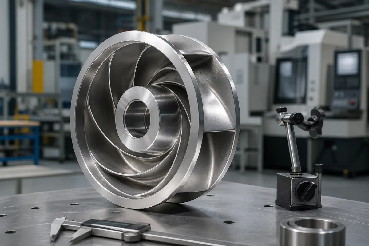
Impeller with a front shroud: how closed impellers are manufactured — cast, machined and brazed, or hybrid-built — and overspeed-tested
How a closed impeller with a front shroud is made and proven · casting, machined parts brazed together, or a milled core built up by laser metal deposition — then balanced and spun to 115% of maximum continuous speed
A closed impeller has a front shroud joined to the vanes, so the flow channels are enclosed between two discs. That shape is what makes it efficient and what makes it hard to make: once the shroud is on, a cutter can only enter the channels through the eye or the outlet. Buyers of new or replacement closed impellers for pumps and centrifugal compressors are therefore choosing a manufacturing route — casting, separate parts joined by welding or brazing, or a hybrid of milling and metal deposition — and then the proof that the finished rotor holds together at speed.
Closed (shrouded) impellers for centrifugal pumps and compressors considered as manufactured parts: casting, fabrication from machined hub, vanes and shroud joined by brazing or welding, hybrid additive-and-milling production, and the balancing and overspeed proof of the finished impeller. Impeller trimming, wear-ring clearances and choosing a balance grade for a pump in service are covered on the Centrifugal pump impeller page; ribbon agitators on the Ribbon blender agitator page; mixing impellers for reactors on the Chemical reactor agitator blade (agitator impeller) page; turbocharger wheels on the Turbine wheel (turbocharger) page; batching systems on the Automated ingredient batching and blending system page.
CNFX editorial research · Sources checked October 12, 2026 · 3 sources
Three ways to make a closed impeller: casting, machined parts joined together, and a milled core grown by metal deposition
Sulzer explains that, because of the geometry of closed pump impellers, casting has so far been the only way to produce them, with risks of small internal and surface defects, limited surface quality and slight geometric inaccuracies that decide how much surface treatment and balancing follow — and lead times that remain long even for rapid casting. [1]
Flowserve's patent explains why its brazed route helps: the parts are machined so their contacting surfaces mate without significant voids, which fixes the joint gap and allows brazing rather than welding; it lists other known routes as well — vanes formed in moulds filled with weld material on a hub, vanes welded between hub and shroud, and cast parts assembled afterwards. [2]
Sulzer's hybrid process works because the core is milled while its radial size is still smaller than the finished impeller, so every channel is reachable; the outer geometry is then added and finish-milled. Sulzer adds that LMD can also lay a wear-resistant coating where a wear ring would otherwise be fitted. [1]
Editorial calculation: 48 hours against 25–35 days is a reduction by a factor of about 12.5 to 17.5. The 48-hour figure was Sulzer's stated goal for mid-2018, not a measured delivery; ask any supplier offering a hybrid or additive impeller for its actual lead time and inspection record. [1]
Route
How the shroud and vanes come together
Published points
Casting
Hub, vanes and shroud poured as one piece
Internal and surface defect risk; limited surface quality; 25–35 days production time cited by Sulzer [1]
Machined hub/vanes + shroud, electron-beam welded
Two pre-formed parts positioned on a five-axis machine and EB-welded
Described as expensive with long lead times; the weld does not join each vane fully from side to side, leaving crevice-erosion potential [2]
Machined shroud, core and hub, brazed (Flowserve patent)
Three parts turned with mating surfaces; vanes cut from the core by five-axis water jet or wire EDM; brazed
Brazing foil or paste 0.002–0.003 in thick; 3 to 7 vanes formed in the example [2]
Hybrid: milled core + laser metal deposition (Sulzer)
Small wrought billet milled on 5 axes, then built up radially by LMD and milled again, repeated as needed
Deposition rate 5–15 times that of selective laser melting; goal of closed impellers within 48 hours [1]
Ask which route the impeller is made by, the material form (casting, forging, wrought billet, deposited powder), how the shroud is joined to the vanes, what non-destructive testing covers the joints or castings, and the quoted lead time.
02
The shroud-to-vane joint: gap, filler thickness and where the patent says welds fall short
In a fabricated closed impeller the strength of the part depends on the joint between vane tips and shroud. Flowserve's patent US 6,276,899 B1 (filed 5 November 1999, granted 21 August 2001) machines each part on a CNC lathe so that the vanes' surfaces mate with the hub on one side and the shroud on the other, and marks the vane positions on the hub with the turning tool using a lathe with a U axis. [2]
The patent prefers brazing foil 0.002 to 0.003 in thick, or brazing paste applied at the same thickness, between the mating surfaces; it notes that the weight of the shroud on the vanes is enough to bring it into alignment before joining. [2] Editorial calculation: 0.002–0.003 in is about 0.051–0.076 mm.
Editorial note: for any fabricated impeller, ask how the joint was inspected — the patent's criticism of electron-beam welding is precisely that a partial joint across the vane leaves a crevice, which an outer inspection does not show.
03
Proof at speed: balancing to G0.67 and spinning to 115% of maximum continuous speed for one minute
Writing in Turbomachinery Magazine, Siemens Gas and Power engineers Mark Kuzdzal and Martin Maier state that, to meet API 617, compressor impellers must be individually balanced and oversped to 115% of the maximum continuous operating speed (MCOS) for one minute. In the hydrogen-recycle compressor they describe, impellers were balanced to API 617 8th Edition (ISO 1940/1 G0.67) before each overspeed run. [3]
Editorial calculation: 5,780 ÷ 5,026 = 1.150, the 115% overspeed. 8.0 mils is about 0.20 mm.
The third-stage impeller tripped at about 4,800 rpm, below its 5,780 rpm target, with vibration rising faster than the speed-squared trend expected from unbalance alone. The authors traced it to an inertia-dominant resonance of the impeller-and-mandrel assembly as the ratio of polar to transverse moment of inertia approached 1.0, advise also avoiding ratios between 0.95 and 1.0, and passed the test by mounting the impeller shroud-down and later with a redesigned one-piece mandrel. [3]
Editorial note: an overspeed trip is not always a fault in the impeller; ask the supplier for the overspeed record (speed reached, hold time, vibration trace) and for post-spin dimensional and crack checks, rather than a single pass/fail line.
Item in the Siemens case
Value
Compressor
Radially split, beam-style, five-stage, straight-through; direct steam-turbine drive at 5,026 rpm [3]
For compressor impellers, ask for the balance grade achieved, the overspeed speed and hold time against MCOS, the vibration record, and inspection after the spin; for pump impellers, agree whether any overspeed or spin test applies at all.
04
Data for a closed impeller enquiry
Paste it into your enquiry below or into an email to a maker, then replace every bracket.
Duty: [pump or compressor; speed; maximum continuous speed]
Geometry: [drawing or sample; diameter; eye and outlet width; vane count]
Material: [grade; casting, forging or wrought billet]
Route: [cast; machined and brazed; welded; hybrid additive-and-milled]
Joints: [filler; inspection method]
Balance: [grade]
Proof: [overspeed percentage and hold time; post-spin inspection]
Lead time: [required date]
Explore company information and manufacturing capabilities, then discuss the scope of your project with a relevant supplier.
Share this page
Compiled and source-reviewed by the CNFX editorial team.
Each manufacturer above links to the page on that company's own website where the product is listed, with the date we checked it. How we source and review
· Page last updated 13 October 2026
Buyer questions
How are closed impellers made?
Sulzer says closed pump impellers have been cast; Flowserve's patent machines hub, vanes and shroud separately and brazes them; Sulzer's hybrid route mills a core and builds the rest by laser metal deposition before finish milling. [1][2]
What overspeed test does API 617 require for compressor impellers?
Siemens engineers state that each impeller must be balanced and oversped to 115% of maximum continuous operating speed for one minute. [3]
How thick is the braze in a fabricated impeller?
Flowserve's patent prefers brazing foil or paste 0.002 to 0.003 in thick between the machined mating surfaces. [2]
Why might an impeller trip an overspeed machine?
In a case described by Siemens engineers, the impeller-and-mandrel assembly had a polar-to-transverse inertia ratio of 1.05, inside the 0.70–1.20 range the machine maker advised avoiding, causing an inertia-dominant resonance. [3]
Sources and what still needs a direct check
Sources checked 2026-10-12. Casting limits and the hybrid route come from Sulzer's 2017 annual-report feature on closed impeller manufacturing; the fabricated route and its joint from Flowserve's US patent 6,276,899 B1; the overspeed requirement and test case from Siemens Gas and Power engineers writing in Turbomachinery Magazine.