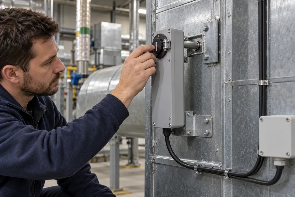
Spring-return output actuator: the electric damper and valve actuator that drives to its safe position when power is removed
Fail-safe final element · Spring-return electric rotary actuators for dampers and quarter-turn valves: return time, torque, cycle life and commissioning checks
An output actuator, in the sense used here, is the last element in a control system's fault response: the electric actuator that physically moves an air damper or a quarter-turn valve. In the spring-return type a mechanical spring is wound while the motor drives, and when the supply is removed it turns the output back to a mechanical zero position without any power. Buyers need to fix which direction is safe, how fast the spring must get there, how much torque remains at the end of the spring stroke, how many spring returns the design life allows, and how the safe position is proved at commissioning.
Electric spring-return rotary actuators of a few newton-metres for air dampers, quarter-turn ball and butterfly valves and linkage-driven globe valves, used as the fail-safe output of a building or process control system. Self-contained electro-hydraulic actuators are covered on the Hydraulic actuator page, pneumatic spring-return heads on the Pneumatic actuator page, DC screw rod actuators on the Adjustment actuator page, and the relay and transistor outputs that switch actuator supply on the Output module for PLCs page. Label template engine, Report formatter and Alert logging database are software products of the same control-system family and do not move anything.
CNFX editorial research · Sources checked October 17, 2026 · 3 sources
The spring acts when the supply is removed, not when the signal is wrong
Regin's RDAS7S data sheet describes the function plainly: with supply voltage connected the actuator moves to the working position set by its 2-point or 0…10 V signal, and on power failure or when the operating voltage is switched off the spring return moves it to its mechanical zero position. Regin names ventilation sections where the actuator must move to the zero, or emergency, position during power failure as one application. [1]
Honeywell's guide specification for its S05 series (MS4105, MS7505, MS8105) asks for either clockwise or counterclockwise fail-safe operation with a continuously engaged mechanical return spring that returns the actuator to a fail-safe position within 20 seconds of power loss, and for a means of manually positioning the output hub without power. Its feature list gives a field-selectable spring return direction and manual winding with a locking function. [2]
Both documents tie the spring action to the supply, so a control system that wants the safe position on a detected fault, rather than only on a power cut, has to switch off the actuator's supply through an output it controls. A modulating actuator that keeps its supply but receives a wrong signal goes where the signal tells it. [1][2]
Regin also states that for mounting the actuator is turned by 180° depending on the required direction of rotation, and that the shaft adapter and parts are not premounted because they are assembled differently for clockwise or counterclockwise damper shafts. [1] The safe direction is therefore set at installation, and the drawing has to show it.
On the drawing for each actuator, mark the safe position, the rotation that reaches it, the longest acceptable spring time and the output that cuts its supply.
02
Motor running time, spring closing time and the torque left to hold the damper
The two data sheets reviewed separate motor time and spring time, and the spring is the faster of the two in both.
Regin states that two actuators can be tandem-mounted on the same damper to double the torque. [1] Editorial calculation: two RDAS7S units in tandem give 2 × 7 = 14 Nm, which assumes both are mounted, wired and timed as Regin's tandem arrangement requires; the damper maker's torque figure for the damper size still decides whether 14 Nm is enough.
Honeywell's guide specification asks for a run time that is constant and independent of load, temperature and supply voltage within specification. [2] Where a sequence relies on the actuator reaching position within a given time, the specification should quote the time at rated torque and voltage, as Honeywell's timing figures are stated.
Volume control dampers, ball, butterfly and linkage-driven globe valves. [2]
Noise
40 dB actuator, 61 dB spring return (sound power). [1]
Floating/modulating: 40 dBA driving, 50 dBA spring return, maximum at 1 m. [2]
03
Supply, control signal, cycle life and shaft fit to put in the order
Field
Published values
Ask the supplier for
Supply voltage
RDAS7S-24: 24 V AC/DC (20…28 V AC 50/60 Hz / 24…48 V DC); RDAS7S-230: 100…240 V AC. [1]
Model per supply.
Power
24 V models 5 VA (3.5 W running / 2 W holding); 230 V models 7 VA (4.5 W / 3.5 W). [1]
VA for transformer sizing.
Control signal
2-point or 0(2)…10 V; 0…10 V input resistance > 100 kΩ. [1] 0-10 V, 2-10 V or 4-20 mA with a 500 Ω resistor; 2-10 V feedback on proportional and floating models. [2]
Signal and feedback type.
Design life
Two-position: 50,000 full-stroke cycles and 50,000 spring returns; floating/modulating: 60,000 full-stroke cycles, 1,500,000 repositions, 60,000 spring returns. [2]
Life at your duty.
Ambient
−32…55 °C, 0…95 % RH, IP54. [1] −40 to 60 °C, 5–95 % RH, IP54 European models when mounted on a horizontal shaft with the access cover below it. [2]
Rating at the mounting position.
Damper shaft
Round 6.4…20.5 mm, square 6.4…13 mm, minimum length 20 mm. [1] Round 10 to 27 mm, square 13 to 19 mm, minimum 25 mm. [2]
Shaft size and length.
Auxiliary switches
RDAS7S-…S: 5°…90° range, set at 5° and 85°. [1] Two SPDT end switches fixed at 7° and 85° stroke. [2]
Switches to prove the safe position.
04
Prove the safe position and the full stroke on site
The US Unified Facilities Guide Specification UFGS-23 09 00 (August 2024, Change 1) for HVAC instrumentation and control includes a start-up step in which, with the system in unoccupied mode and fan hand-off-auto switches off, the contractor verifies that all output devices are in their failsafe and normal positions. [3]
Its actuator range check applies a signal to each actuator through the DDC hardware, records the signal levels at the extreme positions, and verifies travel from zero stroke to full stroke within the signal range and in the proper direction; for valve and damper actuators the check is performed under normal system pressures. [3] For a spring-return actuator, adding a timed spring-return test with the supply removed covers the fail-safe action itself, measured against the time agreed in the order.
05
Give the damper or valve, the safe position and the timing together
Paste it into your enquiry below or into an email to a maker, then replace every bracket.
Driven device: [damper area or valve type; shaft size and length; torque required]
Safe position: [open / closed; rotation direction]
Timing: [motor run time; maximum spring return time]
Supply and signal: [24 V AC/DC or 230 V; 2-point, floating or 0-10 V; feedback]
Options: [auxiliary switches; manual override; enclosure]
Life: [expected cycles and spring returns per year]
Explore company information and manufacturing capabilities, then discuss the scope of your project with a relevant supplier.
Share this page
Compiled and source-reviewed by the CNFX editorial team.
Each manufacturer above links to the page on that company's own website where the product is listed, with the date we checked it. How we source and review
· Page last updated 17 October 2026
Buyer questions
When does a spring-return actuator go to its safe position?
Regin's data sheet says the spring moves the actuator to its mechanical zero position on power failure or when the operating voltage is switched off. [1]
How fast is the spring return?
Regin gives 15 s per 90° for the RDAS7S; Honeywell gives a spring close time of 20 s (typ.) for its S05 series and specifies return within 20 seconds of power loss. [1][2]
How is the fail-safe position checked at commissioning?
UFGS-23 09 00 includes verifying that output devices are in their failsafe and normal positions with the system shut down, followed by a zero-to-full-stroke range check. [3]
Sources and what still needs a direct check
Sources checked 2026-10-17. Values come from Regin's RDAS7S product sheet and Honeywell's S05 specification data (form 63-1302, 2005, retrieved from a copy hosted by damper maker Nailor). The commissioning steps are from UFGS-23 09 00, the US Department of Defense guide specification for HVAC instrumentation and control.