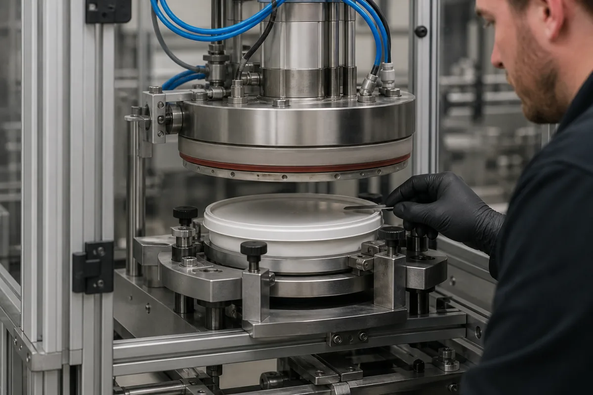
Sealing head for cup and tray lidding machines (heated sealing tool)
Heat-sealing head for cup and tray lidding · Temperature, dwell time and flange pressure, tool face and silicone backing, cylinder force
A sealing head, in the sense used on this page, is the heated upper tool of a cup or tray lidding machine: a temperature-controlled die shaped to the container flange that presses lidding film down onto the flange, against a lower support, for a set time so the sealant layer fuses. Buyers ordering a sealing head or a sealer built around one should check three things first: the temperature and dwell window the lidding film and container need, the pressure the head actually delivers on the flange area, and how the tool face and backing cope with creases or uneven flanges.
Heated sealing heads and sealing tools for cup, tub and tray lidding, including the heated die, lower support with silicone backing, film cutting edge and the pneumatic cylinder that closes them. Instruments that test finished packages for leaks by vacuum decay, pressure decay or bubble emission are covered on the Food packaging integrity (leak) tester page. Induction cap sealers and pressure-test fixtures for bottles are outside this page.
CNFX editorial research · Sources checked October 12, 2026 · 3 sources
Set temperature and dwell inside the film's sealing window
In a study at LUT University, paperboard trays were sealed on a commercial tray sealer whose sealing tool had a heated upper tool and an unheated lower tool with silicone rubber; temperature and sealing time were held at 190 °C and 2.5 s while pressure was varied. [1] A second study from the same group, on a vertical form-fill-seal machine, found the first observable seal at 90 °C for a PE-coated paper material and 100 °C for an OPP/PE film, both at 2 s dwell. The paper material could be sealed up to 220 °C before it began to brown, while the plastic film shrank at 140 °C. [2]
On a laboratory heat sealer the same study found a minimum dwell time of 0.4 s at 100 °C for the paper material; it also reports a sealing tool surface temperature repeatability of ±0.2 °C, and seal strength tested to ASTM F88. Its authors held pressure at 5 bar during the main trials, citing earlier work that raising pressure does not considerably enhance seal strength. [2]
Editorial note: these windows belong to the materials tested. Ask the lidding-film supplier for its seal-strength curve against temperature at your dwell time, and ask the sealer maker to show the head holding that temperature across the whole flange.
Give the supplier the container drawing (flange width, outer diameter or tray outline, flange flatness), container material, lidding film grade and datasheet, target seal strength and peel type, cups or trays per minute, number of lanes, and whether the head also cuts the film.
02
Size the pressure on the flange, not the air supply
The LUT tray study raised the sealer's pressure with a booster and regulator and sealed at 4 bar, 6 bar and 10 bar, which it states correspond to 1.8, 2.7 and 4.5 N/mm² on the flange; the authors describe 6 bar as the industrial standard and note earlier work showing paperboard trays need more than 1.8 N/mm² for a leakproof seal where crease depth in the sealing area is up to 150 µm. Trays sealed at 10 bar had the lowest oxygen content in storage. [1]
Editorial calculation: a round cup with a 95 mm outer flange diameter and a 5 mm flange width has a sealing area of π × (47.5² − 42.5²) ≈ 1,414 mm². Holding 2.7 N/mm² on that area needs about 3.8 kN. At 0.6 MPa air, a cylinder delivering 3.8 kN needs a piston area of about 6,360 mm², a bore of about 90 mm, before friction losses. Cup dimensions are an assumed example. [1][3]
In the VFFS study, force and contact area set the jaw pressure: the same 2,356 N gives 3.8 bar on 6,160 mm² and 3.1 bar on 7,616 mm². The paper's text and its table pair these pressures with the flat and serrated profiles in opposite order, so confirm the tool-face pressure with the machine maker. [2]
03
Compare sealing heads by tool face and machine
The reviewed sources describe three arrangements of the heated tool.
Editorial calculation: at the stated 1,500 cups per hour on a dual-cup machine, each pair of cups has about 3,600 / 750 = 4.8 s for indexing, filling, lid placement and sealing, so a 2.5 s dwell as in the tray study would take about half of the cycle. [3][1]
Arrangement
What the source describes
Ask about
Tray sealer with heated upper tool
Heated upper tool against unheated lower tool with silicone rubber; blade cuts the film to the tray outline. [1]
Backing hardness; cutting edge life.
Flat or serrated jaws (VFFS)
Two 11 mm tool profiles, flat and serrated, on an industrial VFFS machine. [2]
Profile for your film; pressure per profile.
Rotary cup filler-sealer
Dual heat sealing with pneumatic lid placement; 0–400 °C; about 1,500 cups/h based on 120 ml. [3]
Head count; cup size tooling.
04
Heated die, silicone support, blade and cylinder in a lidding seal head
Explore company information and manufacturing capabilities, then discuss the scope of your project with a relevant supplier.
Share this page
Compiled and source-reviewed by the CNFX editorial team.
Each manufacturer above links to the page on that company's own website where the product is listed, with the date we checked it. How we source and review
· Page last updated 13 October 2026
Buyer questions
What temperature and dwell does a lidding seal need?
It depends on the materials; one tray study used 190 °C for 2.5 s, and a VFFS study found first seals at 90–100 °C with 2 s dwell. [1][2]
How much pressure should the head put on the flange?
The tray study sealed at 1.8, 2.7 and 4.5 N/mm²; a 1,414 mm² cup flange at 2.7 N/mm² needs about 3.8 kN (editorial calculation). [1]
What air supply does a cup sealer need?
One rotary cup filler-sealer lists 0.5–0.8 MPa. [3]
Sources and what still needs a direct check
Sources checked 2026-10-12. Leminen et al. and Merabtene et al. are peer-reviewed studies from LUT University published in BioResources; Zonesun is a packaging machine maker publishing its own machine data.