Editorial Technical Reference

Steam Distribution System

This page explains how Steam Distribution System is classified within Machinery and Equipment Manufacturing. Technical values and manufacturer relationships are research references; confirm the current specification and supplier evidence for each order.

Technical Definition & Core Assembly

A network of pipes, valves, and controls that transports steam from generation sources to various points of use within an industrial facility.
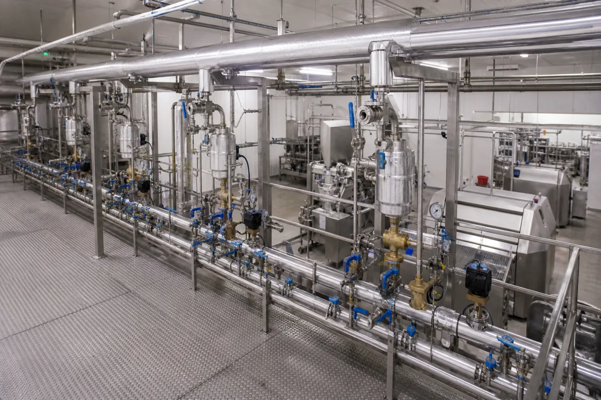
Steam Distribution System in a manufacturing environment
Representative product image. Confirm appearance and specifications with the manufacturer.

Product Specifications

Technical details and manufacturing context for Steam Distribution System

Definition
The Steam Distribution System is a critical component of industrial infrastructure that efficiently delivers steam at required pressures and temperatures to multiple process equipment, heating applications, and utility points throughout a facility. It ensures controlled steam flow while minimizing energy losses and maintaining operational safety. This system typically includes insulated piping networks, pressure-reducing valves, steam traps, control valves, and condensate return mechanisms. It receives high-pressure steam from boilers or steam generators and distributes it to various end-use points. Pressure-reducing valves regulate steam pressure for different applications, while steam traps remove condensate to maintain dry steam quality. Control valves modulate flow based on demand signals from process equipment, and the system maintains thermal efficiency through proper insulation and condensate return. The system is designed for operating pressures of 1.0–1.6 MPa and temperatures of 184–204°C (saturated steam). Nominal diameters range from 25–300 mm (ISO 6708), with flow capacities of 0.5–50 t/h depending on pipe size and pressure. Pressure drop at design flow is ≤0.05 MPa, and leakage rate is ≤0.01% (Class VI seat leakage, ISO 5208). Materials include carbon steel piping (ASTM A105) and stainless steel fittings (ASTM A182), with pipe wall thicknesses of 3.2–12.7 mm (Schedule 40 to 80, ASME B36.10). Insulation thickness is 50–100 mm (mineral wool or PUF). Control valve response time is ≤5 seconds from signal to full stroke. Electrical supply is 220/380 V AC, 50 Hz, 3-phase (IEC 60038), with control signal 4–20 mA (IEC 60381). Enclosure protection for electrical components is IP54–IP65 (IEC 60529). Weight ranges from 50–2000 kg per skid, depending on size. All values are reference ranges and must be verified with the legal manufacturer or supplier for specific models and applications.
Working Principle
The system operates by receiving high-pressure steam from boilers or steam generators, then distributing it through insulated piping networks. Pressure-reducing valves regulate steam pressure for different applications, while steam traps remove condensate to maintain dry steam quality. Control valves modulate flow based on demand signals from process equipment, and the system maintains thermal efficiency through proper insulation and condensate return mechanisms.
Common Materials
Carbon Steel Piping, Stainless Steel Fittings
Technical Parameters
ParameterTypical rangeNotes & selection driver
Operating Pressure1.0–1.6 MPaBelow 1.0 MPa the seat load is insufficientISO 5208
Operating Temperature184–204 °CSaturated steam at given pressure
Nominal Diameter25–300 mmCustom sizes availableISO 6708
Flow Capacity0.5–50 t/hDepends on pipe size and pressure
Pressure Drop≤0.05 MPaAt design flow
Leakage Rate≤0.01 %Class VI seat leakageISO 5208
Material GradeA105–F304Carbon or stainless steelASTM A105/A182
Pipe Wall Thickness3.2–12.7 mmSchedule 40 to 80ASME B36.10
Insulation Thickness50–100 mmMineral wool or PUF
Control Valve Response Time≤5 sFrom signal to full stroke
Electrical Supply220/380 V AC50 Hz, 3-phaseIEC 60038
Control Signal4–20 mAAnalog, HART optionalIEC 60381
Enclosure ProtectionIP54–IP65For electrical componentsIEC 60529
Weight50–2000 kgPer skid, depends on size

Ranges are indicative industry figures for RFQ preparation, not a supplier commitment. Confirm every value and standard with the legal manufacturer before ordering.

Components / BOM
  • Steam Header
    Main distribution pipe that collects steam from source and distributes to branch lines
    Material: Carbon steel with insulation
  • Pressure Reducing Valve
    Reduces steam pressure to required levels for different applications
    Material: Stainless steel body with carbon steel trim
  • Steam Trap
    Automatically removes condensate from steam lines while preventing steam loss
    Material: Cast iron or stainless steel
  • Insulation Part
    Minimizes heat loss from steam pipes and maintains steam quality
    Material: Mineral wool or calcium silicate

Industry Taxonomies & Aliases

Commonly used trade names and technical identifiers for Steam Distribution System.

Applied To / Applications

This component is essential for the following industrial systems and equipment:

Industrial Ecosystem & Supply Chain Structure

Complementary Systems
Downstream Applications
Specialized Tooling

Application Fit & Sizing Matrix

Operational Limits
pressure: Up to 150 bar (2175 psi)
flow rate: 0.5 to 50 m³/h per line
temperature: 100°C to 400°C
steam quality: ≥95% dry saturated steam
Media Compatibility
✓ Process heating applications ✓ Sterilization systems ✓ Humidification systems
Unsuitable: Chloride-rich environments (risk of stress corrosion cracking)
Sizing Data Required
  • Maximum steam demand (kg/h)
  • Operating pressure differential (bar)
  • Pipe routing distance and elevation changes

Reliability & Engineering Risk Analysis

Failure Mode & Root Cause
Water Hammer
Cause: Sudden condensation of steam in pipelines due to improper drainage or rapid valve closure, creating destructive pressure waves
Corrosion Under Insulation (CUI)
Cause: Moisture ingress through damaged insulation or improper sealing, leading to hidden corrosion of pipes and components
Maintenance Indicators
  • Audible knocking or banging sounds in pipes indicating water hammer or trapped condensate
  • Visible steam leaks at joints, valves, or fittings, especially with white mineral deposits (indicating scale buildup)
Engineering Tips
  • Implement a rigorous steam trap maintenance program with regular testing and replacement schedules to ensure proper condensate removal
  • Install and maintain proper pipe supports and expansion joints to accommodate thermal expansion and prevent stress-induced failures

Indicative industry ranges for design and RFQ preparation. Confirm the exact figures and applicable standard with the manufacturer before specifying.

Compliance & Manufacturing Standards

Applicable Standards
ASME B31.1 - Power Piping EN 13480 - Metallic Industrial Piping

Quoted from the published standard.

Manufacturing Precision
  • Pipe Wall Thickness: +/-10% of nominal thickness
  • Flange Flatness: 0.1mm across sealing surface
Quality Inspection
  • Hydrostatic Pressure Test
  • Radiographic Testing (RT) of Welds

Manufacturers of Steam Distribution System

Manufacturer profiles associated with Steam Distribution System.

Sourcing Steam Distribution System from China?
Tell us your specification and target quantity — we will match it against manufacturer records and come back with the factories that fit.
Request manufacturers We manufacture this

Manufacturer listings support early research and capability understanding. They are not certification, ranking, or transaction guarantees.

Share this page
Technical documentation
Request current drawings, revision history, and a signed specification sheet.
Manufacturing capability
Verify equipment lists, process limits, capacity, and representative production evidence.
Inspection readiness
Confirm test methods, calibrated equipment, sampling plans, and traceable reports.
Supplier transparency
Check the legal entity, factory address, ownership, certifications, and direct contacts.

CNFX does not score or rank suppliers. Buyers must verify all claims and documents with the legal manufacturer before ordering.

Supply Chain Commonly Integrated Components

Drive Motor

Electric motor that provides rotational power to drive the blending mechanism in pharmaceutical powder blending equipment

Explore Specs →
Air Handling Unit

A device that conditions and circulates air as part of a heating, ventilation, and air conditioning (HVAC) system

Explore Specs →
Cleaning-in-Place (CIP) System

An automated cleaning system that cleans processing equipment without disassembly, using spray nozzles, pumps, and cleaning solutions to remove residues and contaminants.

Explore Specs →
Vacuum System

A vacuum system that creates and maintains a controlled low-pressure environment for lyophilization by removing air and moisture from the chamber.

Explore Specs →

Frequently Asked Questions

What are the typical operating pressure and temperature ranges for this steam distribution system?

The reference operating pressure is 1.0–1.6 MPa, and the operating temperature is 184–204°C for saturated steam at that pressure. These are directory reference ranges; the actual values must be confirmed with the legal manufacturer or supplier for the specific model and application.

What materials are used in the construction of the steam distribution system?

The system uses carbon steel piping (ASTM A105) and stainless steel fittings (ASTM A182). Pipe wall thickness ranges from 3.2 to 12.7 mm (Schedule 40 to 80, ASME B36.10). Insulation is typically mineral wool or PUF with a thickness of 50–100 mm. Verify material grades and thicknesses with the supplier.

How is the steam distribution system controlled?

Control valves modulate steam flow based on demand signals from process equipment. The control signal is 4–20 mA (IEC 60381), and the response time from signal to full stroke is ≤5 seconds. Electrical supply is 220/380 V AC, 50 Hz, 3-phase (IEC 60038). Enclosure protection for electrical components is IP54–IP65 (IEC 60529).

What are the key performance indicators to verify before purchasing?

Key parameters include flow capacity (0.5–50 t/h), pressure drop at design flow (≤0.05 MPa), leakage rate (≤0.01% per ISO 5208 Class VI), and nominal diameter (25–300 mm per ISO 6708). Always confirm these values with the legal manufacturer or supplier for your specific requirements.

Data Basis

Editorial classification, named public sources where available, and source-reviewed manufacturer records.

Preliminary Technical Classification
This page supports structured research, RFQ preparation, and supplier evaluation. It does not replace buyer-led supplier qualification, standards review, or technical approval.
Buyer enquiry

Request manufacturing insight for Steam Distribution System

Ask for use case, specification boundaries, supplier type, and RFQ preparation information for this product.

Where it goes
Straight to the CNFX editorial desk, and to the manufacturer if this product is linked to a claimed profile. Nothing is broadcast to a supplier list.
Your details stay here
We do not sell or rent enquiry data, and we do not add you to a mailing list. Used only to answer this request.
No commission, no middleman
CNFX is a directory. We take no cut of any order and never negotiate on a supplier's behalf.
What we don't claim
A listing is not an endorsement. Qualify every supplier and verify every figure yourself before ordering.

Your business information is used only to process this request.

Thank you! Your message has been sent. We'll respond within 1–3 business days.
Sorry, we couldn't send your message. Please try again, or email us at [email protected].

Need to Manufacture Steam Distribution System?

Compare manufacturer profiles with relevant product and process capability.

Previous Product
Z-axis Ram/Spindle
Last Product
Get QuotesChat