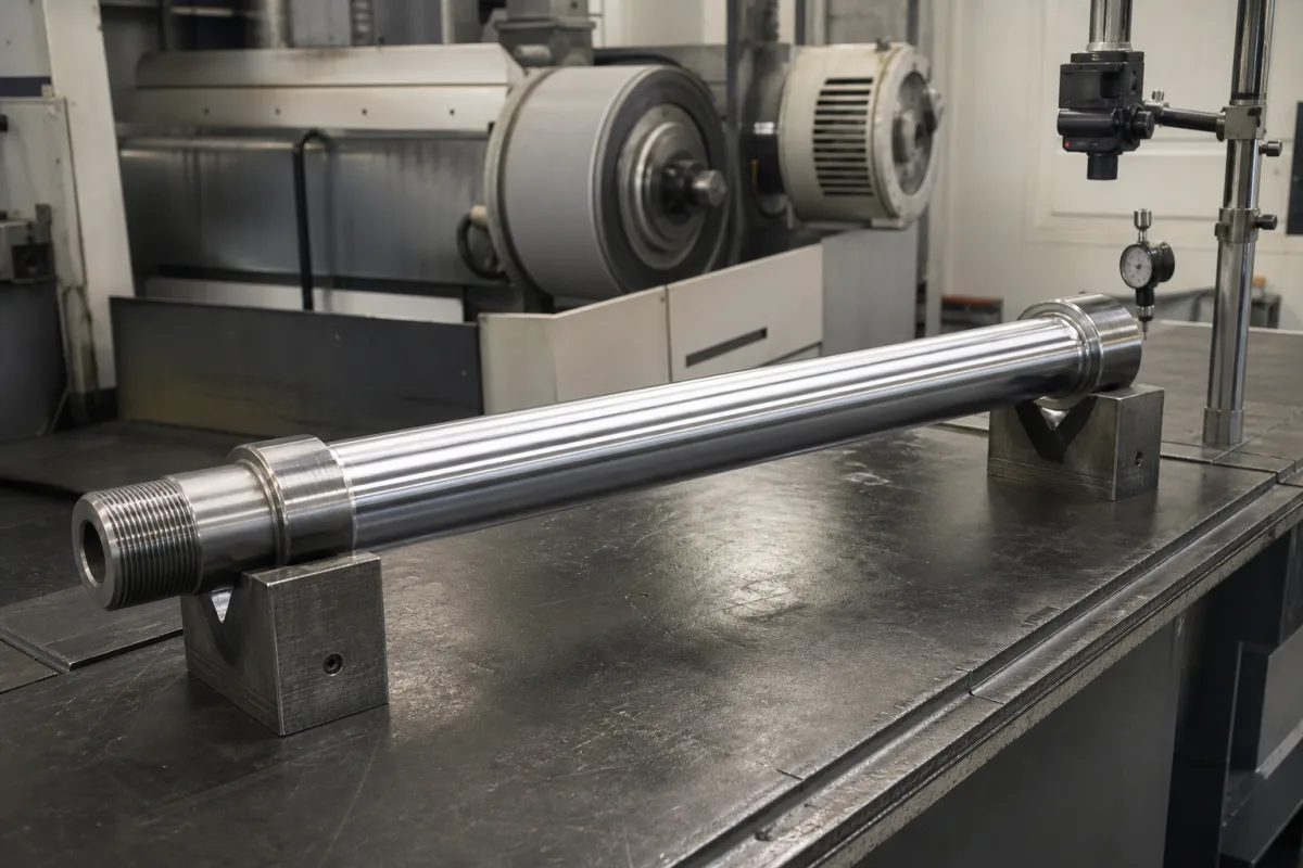
Hollow (bored) hydraulic cylinder piston rod for in-rod position sensors and internal passages
Chrome-plated rod with a bore down its axis · gun-drilled or tube-based rods for an internal position sensor, internal oil or cable routing, or lower moving mass
A hollow piston rod has a bore down its centre line, made by deep-hole drilling a solid rod or by plating and finishing a thick-walled tube. The bore is there for one of three reasons: to take the pressure tube of a rod-style position sensor mounted in the cylinder end cap, so the cylinder reports its own stroke; to carry oil, air or a cable through the rod to the rod end; or to take mass out of a long or fast-moving rod. The outside still has to be the same chrome-plated, ground and polished sealing surface as a solid rod, so the order covers two things: the bore and what goes in it, and the outer surface the seals run on.
Hard-chrome-plated hydraulic and pneumatic cylinder piston rods with an axial bore, gun-drilled from solid or made from chrome-plated tube: bores for rod-style magnetostrictive position sensors, internal fluid or cable passages and mass reduction, with the bore size, wall section, sealing of the bore and the outer chrome surface. Solid chrome-plated rod stock and finished rods, their steel, induction hardening and rod-end machining, are covered on the Hydraulic cylinder piston rod page; the position sensors themselves on the Magnetostrictive linear position sensor page; cylinder barrels on the Hydraulic cylinder body page; complete cylinders on the Hydraulic cylinder page.
CNFX editorial research · Sources checked October 12, 2026 · 3 sources
Bore size and sealing for a rod-style position sensor inside the piston rod
Balluff's installation instructions for its BTL7 rod-style Micropulse transducer, whose waveguide is protected by an outer stainless steel tube, set the minimum bore diameter in the support piston: at least 13 mm for the 10.2 mm diameter tube and at least 11 mm for the 8 mm tube. In a hydraulic cylinder the position magnet must not touch the tube, and the bore must be perfectly sealed with an O-ring or flat seal. [1]
The same instructions call for the transducer flange to sit fully on its supporting surface, fixed with six M6 × 16 cap screws at 3.5 N·m, and for the tube to be supported and, on the 10.2 mm version, screwed at its end when mounted horizontally at nominal lengths over 500 mm. [1] Editorial note: the sensor tube runs the full stroke inside the rod, so the bore depth has to be at least the measuring length plus the sensor's damping zone, and the rod maker needs the sensor drawing before drilling.
Editorial calculation: a 13 mm bore leaves a wall of (D − 13) / 2 around it; in a 40 mm rod that is 13.5 mm, in a 25 mm rod only 6 mm, before any thread is cut at the rod end. Check the rod-end thread root against the bore before choosing the smallest rod that will take the sensor.
Support the tube in horizontal mounting over 500 mm (end screw only on 10.2 mm version) [1]
Send the rod maker the sensor model and drawing, the measuring length, the magnet and its mounting in the piston, and the seal arrangement at the bottom of the bore.
02
What a bore takes from the rod: cross-section, mass and bending stiffness
A central bore removes material where it contributes least to bending stiffness. For a rod of outside diameter D with a bore d, the area falls by the factor (d/D)² and the second moment of area, which governs elastic buckling, by (d/D)⁴.
Editorial calculation for a 50 mm rod: a 13 mm sensor bore removes (13/50)² ≈ 6.8% of the area and therefore of the steel mass per metre, but only (13/50)⁴ ≈ 0.46% of the second moment of area. A 25 mm bore, half the diameter, removes 25% of the mass and 6.25% of the second moment. The bore barely changes column stiffness when it is small; it reduces the area that carries tension and compression stress more.
ISO/TS 13725:2021 is the ISO method for evaluating the buckling load of a hydraulic cylinder. It models the cylinder geometry instead of treating it as an equivalent column, applies to the mountings and rod-end connections in its Table 2, includes a factor of safety set and reported by the person doing the calculation, takes off-axis loading and the cylinder's own weight into account, and assumes the cylinder fully extended. It covers single- and double-acting cylinders to ISO 6020, ISO 6022 and ISO 10762, and states that it is not developed for thin-walled cylinders, double-rod or plunger cylinders, or internal (rod) buckling. [2] Editorial note: a hollow rod's reduced second moment and its wall stress therefore have to be entered by the cylinder designer; the buckling result for a solid rod of the same diameter does not carry over.
Rod OD × bore (mm)
Area and mass removed
Second moment of area removed
50 × 13
(13/50)² ≈ 6.8% (editorial calculation)
(13/50)⁴ ≈ 0.46% (editorial calculation)
40 × 13
(13/40)² ≈ 10.6% (editorial calculation)
(13/40)⁴ ≈ 1.1% (editorial calculation)
50 × 25
25% (editorial calculation)
6.25% (editorial calculation)
Give the cylinder designer the bore diameter and depth, the rod-end thread and the fully extended length so the buckling check uses the hollow section.
03
The outer sealing surface a hollow rod still has to meet
Wuxi Chenna Machinery publishes one specification for its hollow piston rods in CK45 / 1045 steel: diameters 6–300 mm, ISO f7 tolerance, chrome at least 20 µm thick and at least 850 HV, roughness Ra 0.2 µm maximum and straightness 0.2 mm per 1,000 mm. [3]
The maker gives weight reduction, internal passages for hydraulic or pneumatic lines, cables or sensors, heat dissipation and material saving as the reasons for a hollow rod, and lists the checks made before shipment: surface hardness, roughness, chrome thickness, OD tolerance, Charpy impact, salt spray, straightness and mechanical properties. [3] Editorial calculation: at 0.2 mm per 1,000 mm, a 600 mm rod is allowed about 0.12 mm of bow, which a dial indicator on V-blocks can read directly.
Specify the outer diameter and tolerance, chrome thickness and hardness, roughness and straightness exactly as for a solid rod, and add the bore diameter, its concentricity to the outside, the bore depth and the bore finish.
04
Data for a hollow piston rod
Paste it into your enquiry below or into an email to a maker, then replace every bracket.
Purpose of bore: [position sensor model; oil or air passage; cable; mass reduction]
Rod: [OD and tolerance; length; steel grade]
Bore: [diameter; depth; concentricity to OD; through or blind; finish]
Surface: [chrome thickness and hardness; Ra; straightness]
Rod end: [thread; spanner flats; sealing of bore]
Load: [force; fully extended length; mounting for buckling check]
Inspection: [certificates; salt spray; hardness]
1 company lists this product among what they make. Company figures are quoted from each
company's own website; every card states where the relationship came from.
Wuxi Chenna Machinery Co., Ltd.
Manufacturing site to be confirmed for the order
Lists hollow piston rods and hollow chrome-plated bars in CK45 / 1045 steel, 6–300 mm diameter, ISO f7, chrome 20 µm minimum, for internal lines, cables or sensors.
Explore company information and manufacturing capabilities, then discuss the scope of your project with a relevant supplier.
Share this page
Compiled and source-reviewed by the CNFX editorial team.
Each manufacturer above links to the page on that company's own website where the product is listed, with the date we checked it. How we source and review
· Page last updated 13 October 2026
Buyer questions
How big must the bore be for an in-rod position sensor?
Balluff specifies a bore of at least 13 mm in the support piston for its 10.2 mm BTL7 sensor tube and at least 11 mm for the 8 mm tube. [1]
Does a bore weaken the rod against buckling?
Less than it reduces mass: in a 50 mm rod a 13 mm bore removes about 6.8% of the area but about 0.46% of the second moment of area (editorial calculation). ISO/TS 13725 states it is not developed for internal (rod) buckling, so the hollow section must be checked by the designer. [2]
What surface does a hollow chrome rod have?
Wuxi Chenna lists ISO f7, chrome of at least 20 µm and 850 HV, Ra 0.2 µm maximum and 0.2 mm per 1,000 mm straightness for its hollow piston rods. [3]
Sources and what still needs a direct check
Sources checked 2026-10-12. The sensor bore comes from Balluff's installation instructions for a rod-style transducer, the buckling method's coverage from the ISO/TS 13725:2021 abstract, and the hollow-rod surface data from a Chinese rod maker's product page.