Editorial Technical Reference

Precision Industrial Coordinate Measuring Machine

This page explains how Precision Industrial Coordinate Measuring Machine is classified within Manufacture of Measuring, Testing, Navigation and Control Equipment. Technical values and manufacturer relationships are research references; confirm the current specification and supplier evidence for each order.

Technical Definition & Core Assembly

Standalone metrology machine for dimensional inspection of industrial components
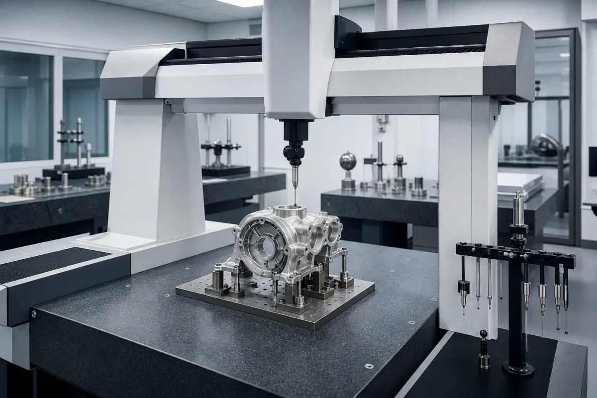
Precision Industrial Coordinate Measuring Machine in a manufacturing environment
Representative product image. Confirm appearance and specifications with the manufacturer.

Product Specifications

Technical details and manufacturing context for Precision Industrial Coordinate Measuring Machine

Definition
A precision coordinate measuring machine (CMM) is a standalone industrial metrology device used for dimensional inspection and geometric verification of manufactured components. It employs a touch-trigger or scanning probe to collect precise coordinate data points from workpiece surfaces. The machine's rigid structure and precision motion system enable accurate measurement of complex geometries, including holes, slots, and contours. CMMs are essential for quality control in manufacturing industries to ensure parts meet design specifications and tolerances. This device is designed for use in manufacturing environments where precise measurement of component dimensions is critical. It features a granite base, aluminum bridge, ceramic guideways, and stainless steel components, providing stability and durability. The measurement volume is 1200×1000×800 mm, with a maximum probing error of ±0.002 mm per ISO 10360-2. Scanning speed ranges from 100 to 300 mm/s, and positioning accuracy is ±0.003 mm/m. The maximum workpiece weight is 2000 kg, and the machine operates within an environmental temperature range of 18–22°C. Resolution is 0.0001 mm, repeatability is ±0.001 mm at 20°C, and maximum acceleration is 500 mm/s². Power supply is 220–240 V AC, 50/60 Hz, single phase. Air supply pressure is 0.4–0.6 MPa, requiring clean, dry air per ISO 8573-1. The machine weight is approximately 4500 kg, and its footprint is 2500×2000×2800 mm. The control cabinet has an ingress protection rating of IP54, while the machine base is IP53. These specifications are reference values and must be confirmed with the manufacturer for specific models and applications.
Working Principle
A motorized probe moves along three orthogonal axes (X, Y, Z) to contact workpiece surfaces. Encoders record precise coordinate positions, which are processed by metrology software to calculate dimensions and geometric relationships. The probe can operate in touch-trigger or scanning mode, collecting data points for analysis. The machine's rigid structure and precision motion system ensure accurate positioning and repeatability. The working principle relies on the integration of mechanical, electronic, and software components to achieve high-precision measurement.
Common Materials
Granite base, Aluminum bridge, Ceramic guideways, Stainless steel components
Technical Parameters
ParameterTypical rangeNotes & selection driver
Measurement Volume (X×Y×Z)Required1200×1000×800 mmMaximum measurable workspace dimensions in three axes
Maximum Probing ErrorRequired±0.002 μmMaximum permissible error for single-point touch-trigger probingISO 10360-2
Scanning SpeedRequired100–300 mm/sMaximum continuous scanning velocity for contour measurement
Positioning AccuracyRequired±0.003 μm/mMaximum error in axis positioning over travel lengthISO 10360-2
Maximum Workpiece Weight2000 kgMaximum permissible weight of measured components
Environmental Temperature Range18–22 °COperating temperature range for specified accuracyISO 10360-2
Resolution0.0001 mmScale resolution.
Repeatability±0.001 mmAt 20°C.ISO 10360-2
Maximum Acceleration500 mm/s²For high-speed scanning.
Power Supply220–240 V AC50/60 Hz, single phase.
Air Supply Pressure0.4–0.6 MPaClean, dry air required.ISO 8573-1
Machine Weight4500 kgApproximate, depends on configuration.
Footprint (L×W×H)2500×2000×2800 mmIncludes stand and controller.
Ingress Protection RatingIP54For control cabinet; machine base IP53.IEC 60529

Ranges are indicative industry figures for RFQ preparation, not a supplier commitment. Confirm every value and standard with the legal manufacturer before ordering.

Components / BOM
  • Granite Base Part
    Provides vibration-damped, thermally stable foundation
    Material: Natural granite
  • Bridge Structure
    Supports X-axis motion system and Z-axis column
    Material: Aluminum alloy
  • Linear Encoders
    Precisely measures position along each axis
    Material: Glass scale with photoelectric reader
  • Touch-Trigger Probe
    Detects contact with workpiece surfaces for coordinate measurement
    Material: Ruby stylus with ceramic shaft
  • Air Bearing System Optional
    Provides frictionless motion with high precision and repeatability
    Material: Porous ceramic with aluminum housing
  • Rotary Table Optional
    Enables multi-axis measurement by rotating workpieces
    Material: Stainless steel with precision bearings
  • Motorized Axis System
    Drives the probe along X, Y and Z under program control.

Industry Taxonomies & Aliases

Commonly used trade names and technical identifiers for Precision Industrial Coordinate Measuring Machine.

Industrial Ecosystem & Supply Chain Structure

Complementary Systems
Downstream Applications
Specialized Tooling

Application Fit & Sizing Matrix

Operational Limits
humidity: 30-60% RH with ±5% stability
vibration: <0.5 m/s² (ISO 10816-3 Grade A)
air quality: ISO 14644-1 Class 8 or cleaner
temperature: 15-25°C (59-77°F) with ±1°C stability
power quality: ±10% voltage stability, <3% THD
Media Compatibility
✓ Aerospace components (aluminum/titanium alloys) ✓ Automotive engine blocks (cast iron/aluminum) ✓ Medical implants (stainless steel/ceramics)
Unsuitable: High-vibration environments near heavy machinery or forging presses
Sizing Data Required
  • Maximum part dimensions (X,Y,Z travel requirements)
  • Required measurement uncertainty (ISO 10360-2 specification)
  • Part material/weight (machine load capacity and probe selection)

Reliability & Engineering Risk Analysis

Failure Mode & Root Cause
Probe Calibration Drift
Cause: Accumulated wear on probe styli from repeated contact, thermal expansion/contraction of probe components, or contamination affecting probe tip geometry, leading to inaccurate measurements.
Linear Axis Positioning Error
Cause: Wear or contamination in linear guideways/ball screws, degradation of encoder feedback systems, or misalignment due to thermal effects or mechanical shock, resulting in positional inaccuracies.
Maintenance Indicators
  • Audible grinding or stuttering noises during axis movement, indicating potential bearing failure or contamination in drive mechanisms.
  • Visual presence of excessive particulate debris or oil mist around guideways or measurement area, suggesting seal failure or contamination ingress.
Engineering Tips
  • Implement strict environmental controls: maintain stable temperature (±1°C) and humidity (40-60% RH), use vibration-isolated foundations, and ensure cleanroom-grade air filtration to minimize thermal drift and contamination.
  • Establish a proactive calibration and verification schedule using certified artifacts, coupled with regular preventive maintenance of guideways, probes, and feedback systems to detect and correct deviations before they impact measurement integrity.

Indicative industry ranges for design and RFQ preparation. Confirm the exact figures and applicable standard with the manufacturer before specifying.

Compliance & Manufacturing Standards

Applicable Standards
ISO 10360-2:2009 - Acceptance and reverification tests for coordinate measuring machines (CMMs) ANSI/ASME B89.4.10360.2 - Performance evaluation of coordinate measuring machines DIN EN ISO 10360-2:2010 - Coordinate metrology - Performance assessment of coordinate measuring machines

Quoted from the published standard.

Manufacturing Precision
  • Length measurement uncertainty: ≤ (0.9 + L/350) μm, where L is measurement length in mm
  • Probing error: ≤ 0.5 μm
Quality Inspection
  • Volumetric accuracy verification using calibrated ball bars or step gauges
  • Repeatability testing through multiple measurements of reference artifacts

Manufacturers of Precision Industrial Coordinate Measuring Machine

Manufacturer profiles associated with Precision Industrial Coordinate Measuring Machine.

Sourcing Precision Industrial Coordinate Measuring Machine from China?
Tell us your specification and target quantity — we will match it against manufacturer records and come back with the factories that fit.
Request manufacturers We manufacture this

Manufacturer listings support early research and capability understanding. They are not certification, ranking, or transaction guarantees.

Share this page
Technical documentation
Request current drawings, revision history, and a signed specification sheet.
Manufacturing capability
Verify equipment lists, process limits, capacity, and representative production evidence.
Inspection readiness
Confirm test methods, calibrated equipment, sampling plans, and traceable reports.
Supplier transparency
Check the legal entity, factory address, ownership, certifications, and direct contacts.

CNFX does not score or rank suppliers. Buyers must verify all claims and documents with the legal manufacturer before ordering.

Frequently Asked Questions

What is the measurement volume of this CMM?

The measurement volume is 1200×1000×800 mm (X×Y×Z). This defines the maximum workspace dimensions for measuring components.

What is the maximum probing error?

The maximum probing error is ±0.002 μm, as per ISO 10360-2. This indicates the accuracy of single-point touch-trigger probing.

What environmental conditions are required for specified accuracy?

The machine operates within an environmental temperature range of 18–22°C to achieve specified accuracy, as per ISO 10360-2.

What is the ingress protection rating?

The control cabinet has an IP54 rating, while the machine base is IP53, per IEC 60529. This indicates protection against dust and water splashes.

Data Basis

Editorial classification, named public sources where available, and source-reviewed manufacturer records.

Preliminary Technical Classification
This page supports structured research, RFQ preparation, and supplier evaluation. It does not replace buyer-led supplier qualification, standards review, or technical approval.
Buyer enquiry

Request manufacturing insight for Precision Industrial Coordinate Measuring Machine

Ask for use case, specification boundaries, supplier type, and RFQ preparation information for this product.

Where it goes
Straight to the CNFX editorial desk, and to the manufacturer if this product is linked to a claimed profile. Nothing is broadcast to a supplier list.
Your details stay here
We do not sell or rent enquiry data, and we do not add you to a mailing list. Used only to answer this request.
No commission, no middleman
CNFX is a directory. We take no cut of any order and never negotiate on a supplier's behalf.
What we don't claim
A listing is not an endorsement. Qualify every supplier and verify every figure yourself before ordering.

Your business information is used only to process this request.

Thank you! Your message has been sent. We'll respond within 1–3 business days.
Sorry, we couldn't send your message. Please try again, or email us at [email protected].

Need to Manufacture Precision Industrial Coordinate Measuring Machine?

Compare manufacturer profiles with relevant product and process capability.

Previous Product
Precision Rotary Encoder Disc
Last Product
Get QuotesChat