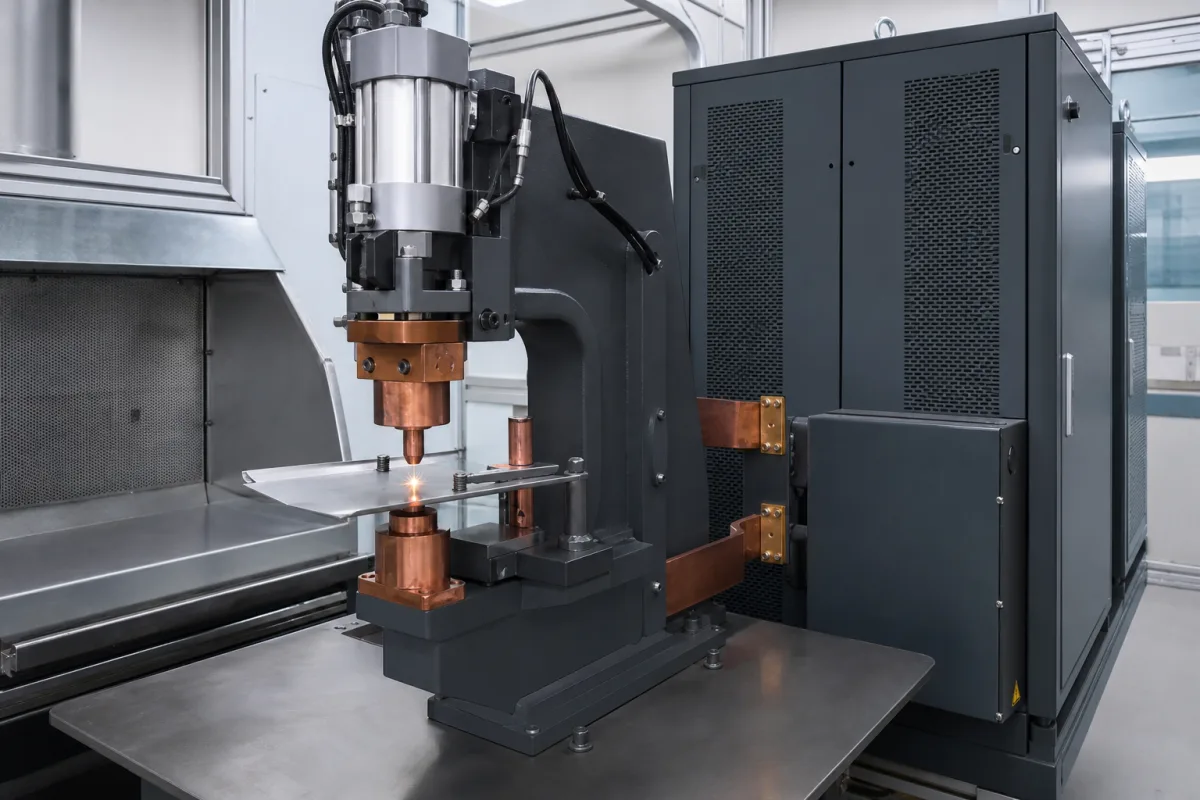
Capacitor discharge (CD) welders · stored-energy resistance and projection welding with E = ½CV², output independent of line voltage, dual-pulse welding, energy ranges from 125 Ws to 12,000 Ws, weld heads and force, and CD stud welding of M3–M12 studs in 1–3 ms
A capacitor discharge (CD) welding machine charges a capacitor bank from the mains and releases it in a very short, high-current pulse to make a weld: in resistance and projection welding the pulse passes through a pulse transformer, weld head and electrodes into the parts, and in CD stud welding it fires through the tip of a stud pressed onto sheet metal. Ask three things first: which process and joint the machine must make, how much stored energy and weld force the parts need, and how repeatable and monitored each pulse is.
Capacitor discharge resistance and projection welding power supplies with weld heads, and capacitor discharge stud welding controllers with contact or lift-gap guns. AC, inverter and linear DC resistance welders, drawn-arc stud welding and spot-welding robots are outside this page except where compared.
CNFX editorial research · Sources checked October 11, 2026 · 4 sources
AMADA WELD TECH describes capacitive discharge welders as stored-energy power supplies that draw energy from the line over time and store it in welding capacitors, so effective weld output is independent of line voltage fluctuations; in the weld cycle the stored energy is rapidly discharged through a pulse transformer, and current flows through the weld head and workpieces. CD power supplies are rated by stored energy and welding speed; stored energy in watt-seconds (joules) is one-half the capacitance times the square of the applied voltage, and the energy delivered to the electrodes is lower because of losses in the primary and secondary circuits. A dual-pulse option uses a first pulse to displace oxides and plating and a second to fuse the base materials. It lists benefits of repeatable output, fast energy release for conductive materials such as copper and small heat-affected zones, and a range from up to 125 Ws to 3,000–12,000 Ws. [1] Its CD projection cap-welding system pairs power supplies of 1,000–9,000 J with pneumatic weld heads giving 120–1,200 lb (single head) or up to 4,000 lb (dual head), with a weld-fire lockout that stops firing if the capacitor charge differs from the set point. [2]
Editorial calculation: with E = ½CV², a 132,000 µF bank charged to 100 V stores 0.5 × 0.132 F × 100² = 660 J, and a 66,000 µF bank at the same voltage stores 330 J; doubling voltage quadruples energy. The capacitances match the stud welders below, but the 100 V charge is an assumed example, and delivered energy is lower than stored.
Give the supplier the process (projection, resistance spot, cap sealing or stud welding), materials, thicknesses and coatings, joint and projection design or stud size, required stored energy and repeat rate, weld force and head type, electrode or chuck tooling, dual-pulse or monitoring needs, atmosphere or enclosure interlocks, supply voltage, cycle rate, automation interface, safety and CE or other marking.
02
Choose projection or stud welding
Soyer, a stud welding maker, describes capacitor discharge stud welding as suitable for studs up to M12, with the capacitor bank discharged in 1–3 ms through the stud's ignition tip: the tip touches the workpiece, an arc forms a thin melt zone on stud and sheet, and the stud is plunged into the weld pool. It lists advantages of stud welding including use on thin sheet with little or no reverse-side marking, no drilled holes and access from one side only. [3] Taylor Studwelding lists CDM capacitor discharge controllers for mild steel, stainless steel, aluminium and brass studs, with contact and lift-gap guns: one model of 66,000 µF welds 2–8 mm mild steel studs and another of 132,000 µF welds 2–10 mm; it describes CD stud welding as suited to flat, clean, thin-gauge parent material with minimal marking, and its lift-gap gun gives up to 5 mm of lift. [4]
Editorial note: for projection welding, ask for weld trials on your parts with the specified projection shape and force; for stud welding, confirm stud standard, material pairing and minimum sheet thickness against the supplier's welding range table.
03
CD resistance supplies, cap-sealing projection systems and portable stud welders
Types include CD resistance welding power supplies with separate weld heads, integrated CD projection systems for hermetic cap sealing, and portable CD stud welding controllers with contact or lift-gap guns. [1][2][4]
04
Capacitor bank, charging circuit, pulse transformer, weld head or stud gun, and interlocks
The output side splits by process: resistance and projection welders send the pulse through a pulse transformer and weld head, while stud welders discharge it through a contact or lift-gap gun. [1][4]
Stored energy, capacitance, weld force, stud range and pulse options for a CD welder quotation
Stored energy is not delivered energy: AMADA gives it as ½CV² and notes that circuit losses lower what reaches the weld, so ask for trials on your joint rather than sizing from the capacitor rating alone. [1]
Field
What it means and published values
Ask the supplier for
Stored energy
Examples: ≤125 Ws to 12,000 Ws; 1,000–9,000 J. [1][2]
3 companies list this product among what they make. Company figures are quoted from each
company's own website; every card states where the relationship came from.
Explore company information and manufacturing capabilities, then discuss the scope of your project with a relevant supplier.
Share this page
Compiled and source-reviewed by the CNFX editorial team.
Each manufacturer above links to the page on that company's own website where the product is listed, with the date we checked it. How we source and review
· Page last updated 13 October 2026
Buyer questions
How is the energy of a CD welder calculated?
AMADA WELD TECH gives stored energy as one-half the capacitance times the square of the voltage; delivered energy is lower due to circuit losses. [1]
Why use capacitor discharge welding?
AMADA lists output independent of line voltage, fast energy release for conductive metals like copper, and small heat-affected zones. [1]
How fast is CD stud welding?
Soyer states the capacitor discharges in 1–3 ms through the stud's ignition tip, for studs up to M12. [3]
Sources and what still needs a direct check
Sources checked 2026-10-11. AMADA WELD TECH, Soyer and Taylor Studwelding are welding equipment makers describing their own products and processes; their figures are examples, not limits.