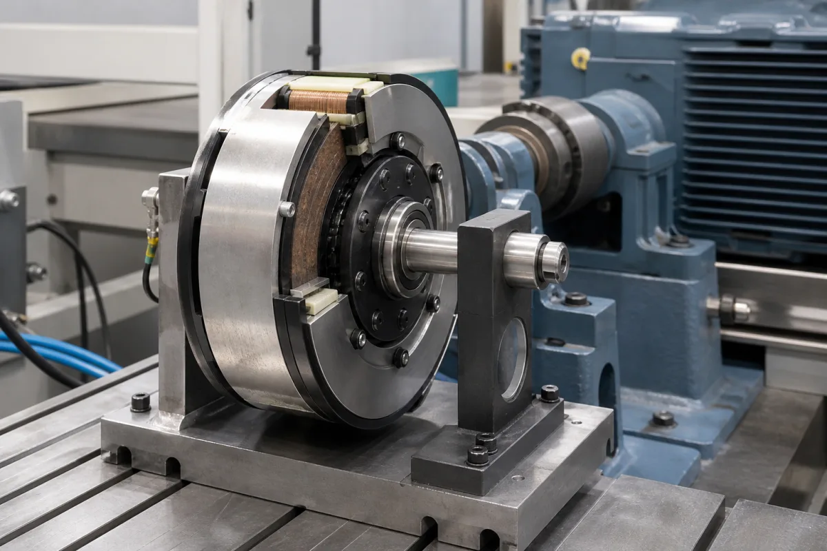
Electromagnetic clutches and brakes · Torque with safety factor, stopping time and inertia, heat per cycle, run-in, DC switching
An industrial electromagnetic clutch-brake unit uses DC coils to pull a steel armature against a friction face, either to couple a driven shaft to a running motor (clutch) or to stop and hold it (brake), and the two can be combined in one housing for start-stop and indexing drives. Ask three things first: what torque the unit must transmit including load friction and inertia, how much heat each start or stop generates at your cycle rate, and how it is switched and run in to reach rated torque and response.
Electromagnetically actuated single-disc, multi-disc and tooth clutches and brakes, power-on and spring-applied (electrically released), and clutch-brake combinations for industrial drives. Pneumatic, hydraulic and mechanical clutches, motor brakes sold only as motor options, and vehicle clutches are outside this page.
CNFX editorial research · Sources checked October 12, 2026 · 4 sources
Warner Electric's sizing guide lists, in order, transmissible torque, energy source, actuation mode, operating environment, heat dissipation and mounting orientation. It distinguishes static torque (at zero relative speed), dynamic torque during acceleration or deceleration, and residual torque in non-energised multi-disc units. Nominal torque is Mn = 9550 · P / n (Nm, kW, min⁻¹); where the real torque is unknown it multiplies this by a safety factor K of 2.5–3 for electric motors, 4–5 for diesel engines and 5–6 for compressors. [1]
For an accurate selection it adds the load torque Ml to the acceleration or deceleration torque Md = J · n / (9.55 · t), where J is the total inertia in kg·m² including reflected inertias and the unit's own parts; the unit's nominal torque must exceed the total. The real time is t = J · n / (9.55 · (Mn ± Ml)), with minus for a clutch and plus for a brake. It permits tooth clutches only for engagement at zero speed difference, applies K = 3 to power-on tooth devices, and forbids them for lifting. [1]
Editorial calculation: a 2.2 kW motor at 1,450 min⁻¹ gives Mn = 9550 × 2.2 ÷ 1450 ≈ 14.5 Nm, or about 36–43 Nm with K = 2.5–3. A 40 Nm brake stopping 0.05 kg·m² from 1,450 min⁻¹ against an assumed 2 Nm of load friction takes about 0.05 × 1450 ÷ (9.55 × 42) ≈ 0.18 s. [1]
Give the supplier the drive power and speed, load torque, total inertia at the unit's shaft, required start and stop times, cycles per minute, mounting (shaft, flange, motor C-face) and orientation, environment (dry, oil, dust), supply voltage and switching, and whether the brake must hold on power loss.
02
Check heat per cycle, run-in and switching
Warner Electric states that friction turns mechanical energy into heat that the unit must absorb without damage, and gives the energy per engagement as W = (J · n² / 182.5) · (Mn / (Mn ± Ml)) joules, to be checked against each product's heat dissipation diagram; if size by heat differs from size by torque, it advises the larger. Dry units are recommended for −25 to +40 °C; lubricated multi-disc units suit high energy per cycle, with oil below 40 cSt at 50 °C. [1]
It notes that friction torque ratings assume 'run in' conditions: new units may transmit below 50% of nominal torque, reached after a run-in of repeated operations with a differential speed above 1 m/s, so a run-in is recommended for positioning precision and rapid acceleration. Its electric units run on DC or rectified AC at standard 24, 103.5 and 207 V; switching on the AC side is 5 to 6 times slower than on the DC side, some electrically released devices use a bi-voltage supply, such as 103.5/48 or 207/103.5 V DC, with the higher voltage for engagement and the lower to hold, and the back EMF at switch-off should be suppressed. [1]
Editorial calculation: in the stopping example above, each stop dissipates about 0.05 × 1450² ÷ 182.5 × 40 ÷ 42 ≈ 550 J; at 10 stops a minute that is about 5.5 kJ per minute, or roughly 90 W average, to compare with the selected unit's heat dissipation diagram. [1]
03
Compare combined clutch-brake units with spring-applied brakes
Kendrion's INTORQ 14.800 is a ready-to-install clutch-brake combination in a single housing for clocked drives at mains-synchronised motor speed: dry-running, backlash-free, engaged by applied DC voltage, in five sizes with rated torques from 7.5 to 120 Nm, insulation temperature class B (130 °C) and a patented wear-adjustment mechanism for resetting the air gap. [2]
Where the drive must hold or stop when power is lost, Kendrion's spring-applied (fail-safe) brakes cover torque from 0.22 Nm (Servo Line, for servo motors) through 1.5–600 Nm (BFK458, for IEC gear motors) and 4–125 Nm (BFK457, for industrial trucks and AGVs) to 100–2,400 Nm (BFK468, for hoists and demanding emergency stops). [3]
Editorial calculation: the 36–43 Nm sized for the 2.2 kW example above falls inside the 14.800's 7.5–120 Nm span and the BFK458's 1.5–600 Nm span; choose between them on whether the brake must apply on power loss, then on heat per cycle. [2][3][1]
04
Check stopping time where the unit drives a power press
Where a clutch-brake drives a mechanical power press in the United States, OSHA's 29 CFR 1910.217 sets duties that fall on the clutch-brake and its control. On part-revolution clutch machines the clutch shall release and the brake shall be applied when the external clutch engaging means is removed, deactivated or deenergized, and a red stop control shall immediately deactivate the clutch and apply the brake. The brake capacity shall be sufficient to stop the slide quickly and to hold it at any point in its travel. [4]
Stopping time sets guard distance: for presence-sensing devices and two-hand controls the safety distance is Ds = 63 inches/second × Ts, where Ts is the press stopping time measured at about 90° of crankshaft rotation. A required brake monitor must prevent the next stroke if stopping time or braking distance deteriorates past that safety distance, and must check brake performance on each stroke. For presses in presence-sensing device initiation (PSDI) mode the brake monitor setting shall allow an increase of no more than 10 percent of the longest stopping time, or 10 milliseconds, whichever is longer, measured at the top of the stroke. [4]
Editorial calculation: a press with a stopping time of 0.20 s (assumed) needs Ds = 63 × 0.20 = 12.6 in (about 320 mm); in PSDI mode the monitor limit is the longer of 0.10 × 200 ms = 20 ms and 10 ms, so 20 ms, which adds 63 × 0.020 ≈ 1.3 in of distance. A clutch-brake whose release and brake times are quoted with your supply (see the switching notes above) feeds this calculation directly. [4][1]
05
Compare what suppliers offer
Suppliers linked to this page list electromagnetic clutches and brakes; each card links to the page reviewed.
Listings include electromagnetic clutch and brake assemblies for industrial drives.
06
Trace the unit components
This is a functional reference built from the sources cited; it is not one maker's specification.
DC switching, overexcitation, back-EMF protection. [1]
Supply type and response.
07
Fill the specification fields with values for your drive
A clutch-brake quotation needs values for your drive. The table explains each field, gives published values where a reviewed source states them, and says what to obtain from the supplier.
Sets Ds = 63 in/s × Ts; PSDI brake-monitor margin 10% or 10 ms, whichever is longer (OSHA). [4]
Measured stop time at 90° and brake-monitor interface.
08
Send the drive, load and cycle data together
Paste it into your enquiry below or into an email to a maker, then replace every bracket.
Drive: [power; speed; motor or engine]
Load: [load torque; inertia at unit shaft]
Motion: [start and stop times; cycles per minute]
Unit: [clutch; brake; combination; power-on or spring-applied]
Mounting: [shaft; flange; orientation; environment]
Electrics: [supply; DC switching; overexcitation]
Explore company information and manufacturing capabilities, then discuss the scope of your project with a relevant supplier.
Share this page
Compiled and source-reviewed by the CNFX editorial team.
Published product pages show what a company offers, not tested performance. Confirm the legal seller, factory and scope for your order. How we source and review
· Page last updated 13 October 2026
Buyer questions
How much torque does a clutch for an electric motor need?
Warner Electric's quick selection multiplies 9550 · P / n by a safety factor of 2.5–3 for electric motors. [1]
Why is a new clutch or brake weaker than rated?
Warner states new friction units may give below 50% of nominal torque until run in with a differential speed above 1 m/s. [1]
Should I switch the coil on the AC or DC side?
Warner notes AC-side switching is 5–6 times slower than DC-side switching. [1]
What torque range do electromagnetic clutch-brake units cover?
Kendrion's INTORQ 14.800 combinations run from 7.5 to 120 Nm in five sizes; its spring-applied brakes span 0.22 to 2,400 Nm across series. [2][3]
How does clutch-brake stopping time affect press guarding?
OSHA 29 CFR 1910.217 sets the safety distance as Ds = 63 inches/second × Ts, with Ts the stopping time measured at about 90° of crankshaft rotation, so a slower stop pushes guards and two-hand controls further from the die. [4]
Sources and what still needs a direct check
Sources checked 2026-10-12. Warner Electric (Altra) and Kendrion are clutch and brake makers; their sizing formulas and figures apply to their own ranges and are a method to apply with your supplier's ratings. OSHA's power-press rule applies where the unit drives a mechanical power press in the United States.