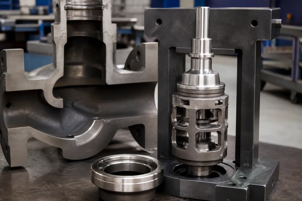
Feedwater control valve trim for steam generators: anti-cavitation cage, plug and seat ring
Replaceable trim for boiler and HRSG feedwater regulating valves · staged anti-cavitation cage for start-up pressure drops, plug and seat ring for Class V shut-off, and a minimum-lift limit
The trim of a boiler or heat recovery steam generator feedwater control valve is the set of replaceable internals — cage, plug, stem and seat ring — that sit between the feed pump discharge and the drum or economiser inlet. At start-up the boiler side is at low pressure, so the trim takes almost the whole pump head at small flow; at full load the pressure difference shrinks and the same valve must pass large flow. Feedwater trim is therefore specified for cavitation at low lift, tight shut-off at the seat, and resistance to the particulate that feedwater carries.
Replacement and new trim sets for feedwater regulating and start-up valves on drum boilers, once-through boilers and HRSGs: staged or drilled-hole anti-cavitation cages, plugs, seat rings, seals and sacrificial trims for pipe blows. Complete pneumatic globe control valves with actuator, positioner, sizing and leakage testing are covered on the Pneumatic globe control valve page; contoured, perforated and hardfaced plugs for any service on the Control valve plug page; low-flow dosing valves on the Low-flow (micro-flow) pneumatic flow control valve page; and molten-metal slide gates on the Slide gate flow control page. The drum the feedwater valve fills — steam drums for water-tube boilers and HRSGs with their internals and nozzles — is covered on the Steam drum for water-tube and waste heat boilers page; this page covers only the valve internals that throttle feedwater on its way to that drum.
CNFX editorial research · Sources checked October 12, 2026 · 3 sources
High pressure drop at low flow during start-up, low drop at high flow at full load
Bailey Japan's patent US5351717 on a boiler feedwater control valve for variable-pressure boilers states the problem the trim must solve. [2]
The valve sits between the high-pressure feed pump discharge and the boiler inlet. At start-up or low load it works under a severe high differential pressure at low flow, because the boiler side is at low pressure; at high load the boiler pressure rises close to the pump discharge pressure and the valve must pass high flow at low differential pressure. When the flow passes the minimum throttling point at low load, static pressure can fall below saturation pressure and cavitate. [2]
The patent's answer is a cage with two passages: a multi-stage set of high-resistance ports that alone are open at low lift, reducing pressure step by step with sharp changes of direction so that cavitation does not form, and a passage with fewer stages that opens at medium and high lift to carry the full-load flow without a separate large low-resistance valve in parallel. The inlet pressure acts on opposing faces of the upper and lower discs, cancelling stem thrust without balancing holes or seals. [2]
Duty in combined-cycle plants adds cycling: an Emerson sales engineer writing in POWER notes plants exceeding 250 starts a year, up to eight critical feedwater valves per HRSG, feedwater valve costs above $160,000 for a two-on-one plant, and feedwater pressures as high as 3,000 psig with F-class gas turbines and above 4,000 psig in some repowering projects. [3]
02
Cage hole geometry: orifice at the inner wall, hole 40–50% of the wall thickness
Copes-Vulcan's patent US4149563 on an anti-cavitation valve for duties such as boiler feedwater gives the proportions of radial cage passages that move the vena contracta, and with it the bubble collapse, away from the cage and plug. [1]
Editorial calculation: the patent's two examples give orifice-to-wall ratios of 2.4/5.5 = 44% and 18/45 = 40%, both inside the claimed 40–50% band.
The patent also recesses the plug's end face so that plug material is kept away from the sites where bubbles implode, and warns that a throttling valve with excessive cavitation can be destroyed within a few hours. [1] In POWER's account, staged trim works only when enough flow passages are uncovered; otherwise the whole drop is taken across the last stage and the seating surfaces. [3]
Passage feature
Value given in US4149563
Orifice position
At the inner (downstream) wall of the cage, so the vena contracta forms in the flow beyond the wall. [1]
Cylindrical land at the orifice
About 0.8 mm long, enough for machining tolerance across valve sizes. [1]
Small valve, 50–75 mm
Orifice about 2.4 mm in a cage wall about 5.5 mm thick. [1]
Large valve, about 350 mm
Orifice about 18 mm in a cage wall about 45 mm thick. [1]
Wall-to-orifice ratio T/D
Optimum above 2:1 and not much beyond 2.5:1; claimed as orifice 40–50% of wall thickness. [1]
Converging cone
30° included angle (15° to the axis) across the size range. [1]
Inlet flare
Radius about twice the orifice diameter; centre about 1.75–1.85 D in from the outer wall. [1]
Send the trim maker the pressure drop and flow at start-up, minimum load and full load, feedwater temperature and the plant's chemistry, and ask for the cavitation check at each point, not only at the design point.
03
Seat ring and shut-off: Class V, 800 lbf per lineal inch of seat load, and no throttling below 10% open
The POWER article traces three seat-related failure routes in feedwater valves: leakage that cavitates across the seating surfaces, throttling too close to the seat, and particulate. [3]
Editorial calculation: for an example 3-inch seat diameter, the seat circumference is π × 3 in = 9.42 in, so 800 lbf per lineal inch means about 7,540 lbf of seat load from the actuator; use the actual port diameter of your trim.
The same article describes gear-tooth erosion at the bottom of plugs exposed to particulate, and plugged anti-cavitation trim that no longer stages the pressure drop, leading to cavitation damage on trim components and, in severe cases, valve bodies. [3]
Issue
Recommendation in the POWER article
Shut-off class
Class V recommended for feedwater valves exposed to cavitation; valves installed at Class IV or less can be upgraded by a trim change. [3]
Seat load
Set the actuation package to provide 800 pounds of force per lineal inch of seat. [3]
Minimum travel
Not below the maker's minimum; rule of thumb not below 10% open, enforced by interlock or low-travel cut-off. [3]
Oversizing
Conservative sizing leaves valves at 30–40% open in normal operation, eroding seats during start-up; retrofit trims can change the characteristic. [3]
Seals
Improved soft seals below 600 °F; metal seals above 600 °F; or unbalanced trim to remove the seal leak path, after checking the actuator. [3]
Particulate
Protected inside-seat designs move the seating surface out of the flow path; larger-passage anti-cavitation trim lets particulate pass; sacrificial trim during pipe blows. [3]
State the leakage class and test, the seat diameter and required seat load, the minimum controllable travel, and whether sacrificial trim is needed for commissioning blows.
04
Process and valve data for a feedwater trim quotation
Paste it into your enquiry below or into an email to a maker, then replace every bracket.
Valve: [make; model; size; body rating; existing trim]
Service: [drum, once-through or HRSG; start-up or main regulating]
Conditions: [inlet and outlet pressure and flow at start-up, minimum and full load; temperature]
Trim: [cage type; stages; characteristic; plug and seat materials; hardfacing]
Shut-off: [leakage class; seat diameter; actuator thrust]
Operation: [starts per year; minimum travel; particulate and chemistry]
Commissioning: [sacrificial trim for pipe blows]
Explore company information and manufacturing capabilities, then discuss the scope of your project with a relevant supplier.
Share this page
Compiled and source-reviewed by the CNFX editorial team.
Each manufacturer above links to the page on that company's own website where the product is listed, with the date we checked it. How we source and review
· Page last updated 13 October 2026
Buyer questions
Why is a feedwater control valve hardest to run at start-up?
At start-up the boiler side is at low pressure, so the valve takes a very high differential pressure at low flow, where static pressure at the throttling point can fall below saturation and cavitate. [2]
What leakage class should feedwater valve trim have?
An Emerson engineer writing in POWER recommends Class V for feedwater valves exposed to cavitation, with 800 lbf per lineal inch of seat load. [3]
How small can the holes in an anti-cavitation cage be?
Copes-Vulcan's patent gives about 2.4 mm holes in a 5.5 mm wall for a 50–75 mm valve and about 18 mm in a 45 mm wall for a 350 mm valve, with holes 40–50% of wall thickness. [1]
Sources and what still needs a direct check
Sources checked 2026-10-12. Two patents from valve makers (Copes-Vulcan and Bailey Japan) describe feedwater cage designs; the operating recommendations come from an article in POWER magazine written by an Emerson sales engineer.