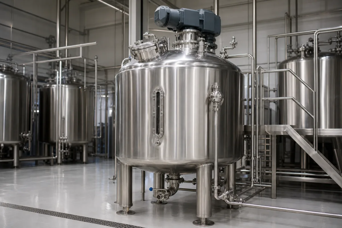
Sanitary mixing vessel construction: the surface finish, radii, drain slope, openings and legs that make an agitated beverage tank cleanable
Hygienic construction of a stainless mixing vessel · 0.8 µm Ra contact surfaces, 19 mm head-to-shell radius, 6.35 mm bottom slope per 305 mm, flanged openings, agitator deflectors and leg clearance
A beverage mixing tank is cleaned in place, with nobody inside it, between batches of syrup, juice or flavoured drink. Whether that works depends less on the agitator than on the shell around it: how smooth the steel and welds are, how tight the corners are, whether the bottom drains completely, how the manway, sight glass and agitator nozzle pass through the head, and whether the floor under the tank can be washed. This page sets out those construction rules with their numbers, so they can be written into a tank specification and checked on delivery.
Construction and hygienic design of stainless agitated mixing vessels for beverages and liquid foods: product-contact finish, welds, internal radii, drainable bottoms, openings, covers, agitator entries and supports. Agitator selection, baffles and power number are covered on the Mixing vessel (agitated mixing tank) for liquids page; the agitator unit itself on the Top-entry hygienic agitator for food mixing tanks page; manway covers on the Sanitary manway page; cleaning devices on the Spray device for automated CIP/SIP page; sugar dissolving on the Sugar syrup preparation and dosing station page.
CNFX editorial research · Sources checked October 13, 2026 · 3 sources
Contact surfaces and welds at 0.8 µm Ra, a 19 mm head-to-shell radius and 6.35 mm in every internal angle under 135°
The USDA Dairy Grading Branch guidelines for the sanitary design and fabrication of dairy processing equipment (02/2022), which draw on 3-A Sanitary Standards, give numeric construction rules for stainless processing tanks. They are written for dairy equipment acceptance; for a beverage tank they serve as a written construction reference. [1]
Gun Wirtanen of the DTU National Food Institute, summarising EHEDG hygienic design practice, puts the internal corner rule differently: sharp corners of 90° or less must be avoided, and corners under 135° must have a radius of at least 3 mm, preferably 6 mm or more. Joints are to be polished to the same roughness as the surrounding surface. [2]
Editorial calculation: the USDA 6.35 mm minimum sits just above DTU's preferred 6 mm, and the 19.0 mm head-to-shell radius is three times the 6.35 mm internal-angle value. A tank built to the USDA figures therefore also meets the 3 mm and 6 mm figures in the DTU summary.
Feature
USDA dairy guideline value
Source
Product-contact surfaces, including welded joints
At least as smooth as 32 µin (0.8 µm) Ra, free of pits, folds, crevices and cracks [1]
USDA 10.1 A
2B mill finish
Accepted on stainless sheet if defect-free; a note treats 2B on plate over 3 mm and on bar as unacceptable for product contact without further surface preparation [1]
USDA 10.1 A
Electropolishing
Accepted only on a surface first brought to 0.8 µm Ra; it does not remove pits, folds or crevices [1]
USDA 10.1 B
Permanent joints
Continuously welded, ground and polished to 0.8 µm Ra [1]
Write into the specification the Ra value for sheet, plate and welds, the head-to-shell radius, the minimum internal radius, whether electropolishing is applied, and how finish will be measured at delivery.
02
A bottom that drains itself: 1/4 in per foot up to 6 ft from the outlet, 1/2 in per foot beyond
USDA requires product-contact surfaces to be self-draining apart from normal adherence, and tank bottoms built so they do not sag or buckle and stop complete drainage. [1]
For equipment 6 ft (1,829 mm) or less in diameter, or in distance to the drain outlet, the bottom must slope at least 1/4 in (6.35 mm) per foot (305 mm); beyond 6 ft, at least 1/2 in (13 mm) per foot. [1] DTU's handout contrasts tanks whose flat or poorly sloped bottoms leave residual soil with self-drainable designs. [2]
Editorial calculation: 6.35 / 305 is a 2.1 % fall (about 1.2°), and 13 / 305 is 4.3 % (about 2.4°). For a 1.5 m diameter tank with a centre outlet, the farthest point of the bottom is 0.75 m from the outlet, so it must sit at least 0.75 / 0.305 × 6.35 ≈ 16 mm above the outlet.
The EHEDG working group on guideline 51 (hygienic design aspects for tank and vessel cleaning), with members from Alfa Laval, GEA, Cargill, Fraunhofer, the University of Cambridge and KU Leuven, lists tank shape, meaning radiused corners and slope, together with surface imperfections, process connections and shadow zones, among the points that decide whether CIP cleaning of a tank succeeds. [3]
Give the tank diameter and outlet position, and ask for the bottom fall in millimetres from the farthest point to the outlet, measured after the tank is set on its legs.
03
Manway, sight glass and agitator entry on the head: outward flanges, umbrella deflectors and a 25 mm bearing gap
Every hole in the head of a mixing vessel is a place where wash water, condensate or dust can run into product, so USDA sets rules for each kind of opening. [1]
USDA also requires covers to be designed so that, when open, liquid on their outer surface and condensate on their underside do not drain into the vessel. [1]
Opening or part
USDA requirement
Openings through a product-contact surface
Permanently attached sanitary connections, or flanged outward at least 3/8 in (9.52 mm) [1]
Covers without gaskets
Downward flange of at least 3/8 in (9.5 mm) along all edges; covers pitched to the outside [1]
Agitators and pipes entering vertically
Sanitary umbrella (downward-curved) deflector overlapping the outward-flanged opening [1]
Agitator bearings
No lubricated bearings in the product area; at least 1 in (25 mm) of open shaft between the bearing seal and the sanitary seal or product opening [1]
Agitator shaft with internal bearing cavity
Cavity diameter greater than its depth; otherwise 3-A 73 for mixers and agitators [1]
To 3-A Sanitary Standard 84; for dry applications at least 15 × 20 in (381 × 508 mm) oval or 18 in (457 mm) round [1]
Bridges and fixed covers
Sloped to the outside edge with a raised flange of at least 3/8 in (9.5 mm); no wider than 24 in (610 mm) [1]
04
Legs and floor clearance: 102 mm under small bases, 152 mm once the footprint is wider than about 635 mm
Legs must leave at least 4 in (102 mm) between the lowest fixed point and the floor when no point of the base outline is more than 12½ in (318 mm) from its nearest edge, and at least 6 in (152 mm) otherwise; adjustable feet follow 3-A Sanitary Standard 88, and a closed base must be sealed to the floor. [1]
Editorial calculation: a round footprint has a point more than 318 mm from its edge once its diameter exceeds 2 × 318 = 636 mm, so the 152 mm clearance applies to a leg-mounted mixing tank of that size or larger.
State the clearance under the lowest outlet valve or pipe, not under the shell, since USDA measures to the lowest fixed point.
05
Hygienic construction data for a mixing vessel quotation
Paste it into your enquiry below or into an email to a maker, then replace every bracket.
Vessel: [working and total volume; diameter; head type]
Material: [stainless grade for shell, heads and nozzles]
Finish: [Ra for sheet, plate and welds; electropolishing yes/no]
Radii: [head-to-shell; internal angles]
Bottom: [shape; fall to outlet in mm]
Head openings: [manway standard; sight glass; agitator entry with deflector]
Supports: [number of legs; adjustable feet; clearance to lowest fixed point]
Cleaning: [CIP devices and coverage test]
Explore company information and manufacturing capabilities, then discuss the scope of your project with a relevant supplier.
Share this page
Compiled and source-reviewed by the CNFX editorial team.
Each manufacturer above links to the page on that company's own website where the product is listed, with the date we checked it. How we source and review
· Page last updated 13 October 2026
Buyer questions
How smooth must the inside of a sanitary mixing vessel be?
USDA's dairy equipment guidelines require product-contact surfaces and welds at least as smooth as 32 µin (0.8 µm) Ra, free of pits, folds, crevices and cracks. [1]
What corner radius does a hygienic tank need?
USDA asks for at least 19.0 mm where head meets shell and 6.35 mm in internal angles under 135°; DTU's EHEDG-based summary gives a 3 mm minimum, preferably 6 mm or more. [1][2]
How much slope does a tank bottom need to drain?
USDA sets at least 1/4 in per foot up to 6 ft from the outlet and 1/2 in per foot beyond. [1]
Sources and what still needs a direct check
Sources checked 2026-10-13. Construction values come from the USDA Dairy Grading Branch guidelines (02/2022), which draw on 3-A Sanitary Standards; corner radii from Gun Wirtanen's DTU National Food Institute handout on EHEDG-based hygienic design; tank cleaning factors from the EHEDG guideline 51 working group's 2022 presentation.