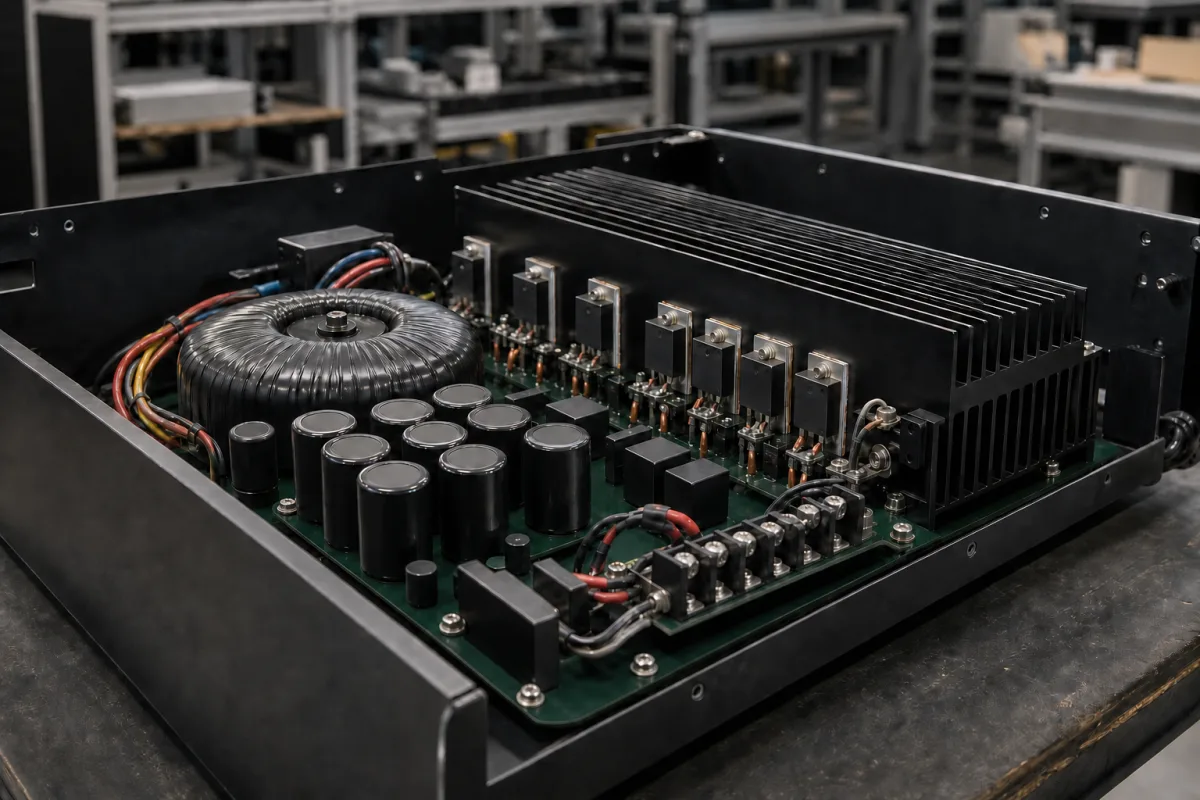
Linear (class AB) amplifier module with toroidal-transformer supply and heat-sunk power ICs
Linear power amplifier boards with a toroidal transformer, reservoir capacitors and power ICs on a finned heat sink · heat, rails and paralleling
A linear amplifier module runs its output devices in their active region, so the heat they shed sets the size of the heat sink, and in the designs cited here its supply is an unregulated split rail from a mains transformer, rectifier and large reservoir capacitors. The board in this class carries all three: a toroidal transformer, a bank of electrolytics and a row of power devices bolted to a finned extrusion. This page works through the thermal limit of one documented power IC, the LM3886, the rail voltages and transformer behind it, and how two or four ICs are combined for 100 to 200 W.
Analog-input linear (class AB) audio power amplifier boards and modules built on monolithic power op-amps or discrete output stages, with an on-board or matched unregulated transformer supply and a heat sink. Class-D and other switching audio amplifier boards are covered on the Audio amplifier module page; complete cased amplifiers, preamplifiers and RF, fibre-optic or load-cell amplifier modules are outside this page.
CNFX editorial research · Sources checked October 12, 2026 · 3 sources
About 40 W of heat per LM3886, and a heat sink near 1.95 °C/W to carry it
TI rates the LM3886 at 68 W continuous average into 4 Ω and 38 W into 8 Ω at ±28 V with 0.1% THD+N from 20 Hz to 20 kHz, and 50 W into 8 Ω at ±35 V, in an 11-lead TO-220 package. [1] Its worst-case dissipation is PDMAX = VCC² / (2π²RL) with VCC the total supply voltage. [1] TI's application report AN-1192 works this out as 39.7 W at ±28 V into 4 Ω and 31.0 W at ±35 V into 8 Ω, and concludes the IC can handle about 40 W of continuous dissipation with proper heat sinking before its SPiKe protection turns on. [2]
The 125 W dissipation rating in the datasheet is derived from θJC = 1 °C/W, a 150 °C junction and 25 °C air, and AN-1192 calls that number misleading for real designs. [2] Its bench results give 40 W without a fan and 60 W with a fan for the non-isolated LM3886T, and 30 W and 45 W for the isolated LM3886TF, whose overmoulded back raises the package thermal resistance to about 2 °C/W. [2] The non-isolated tab sits at V−, so the heat sink is at the negative rail unless a mica washer is added, which raises θCS. [1]
The heat sink is sized from θSA = [(TJmax − TAmb) − PDMAX(θJC + θCS)] / PDMAX, with TJmax = 150 °C, θJC = 1 °C/W and about 0.2 °C/W case-to-sink with thermal compound. [1] Without compound the case-to-sink resistance will be no better than 0.5 °C/W. [1]
Editorial calculation per IC at 25 °C air; a warmer chassis or more than one IC on the same extrusion need a lower θSA. The second row combines AN-1192's approximate 2 °C/W with the datasheet's 0.2 °C/W compound figure.
02
Unregulated ±21 V to ±26.6 V rails for 40 W into 4 Ω, from a toroid that needs a slow-blow fuse
TI's worked design for 40 W into 4 Ω gives a peak output of 17.9 V at 4.5 A; adding the LM3886's 4 V dropout sets the loaded rails at ±21.0 V, and allowing 15% supply regulation and 10% high line gives a maximum of ±26.6 V. [1] The IC does not require a regulated supply, accepts 20 to 94 V total, is limited to 84 V total with an input signal, and stays unbiased while |VEE| + |VCC| ≤ 12 V to avoid turn-on and turn-off transients. [1]
Each rail is bypassed at the package with a 10 µF or larger electrolytic and a 0.1 µF ceramic, and TI asks for 470 µF or more at the terminals to keep rectified load current out of the internal circuitry. [1] In the 200 W bridged/parallel reference design, AN-1192 uses an unregulated bipolar supply with a line filter, surge-protecting MOVs, a separate 385 VA toroidal transformer per channel and 40,000 µF of reservoir capacitance on each rail. [2]
Hammond's 182 series of chassis-mount toroids illustrates the transformer side: the 182M18 is rated 120 VA with 36 V centre-tapped at 3.33 A (18 V at 6.66 A in parallel), and the series is hi-pot tested at 4,000 V RMS between primary and secondary. [3] Hammond warns that a toroid can draw a high magnetising current at switch-on, limited only by the primary's low DC resistance and lasting rarely longer than half a cycle, and recommends a slow-blow fuse, time-delay breaker or soft-start. [3]
Editorial calculation: each 18 V half of an 18-0-18 V winding has an ideal no-load peak of 18 × √2 ≈ 25.5 V, before rectifier drop and transformer regulation, which falls between TI's ±21.0 V loaded and ±26.6 V maximum rails for the 40 W, 4 Ω design. The loaded rail has to be measured on the actual transformer.
03
100 W bridged, 100 W parallel and 200 W bridged/parallel from the same IC
AN-1192 builds higher power by combining LM3886 ICs. Its BR100 bridged circuit holds THD+N below 0.004% from 20 Hz to 1 kHz between 1 W and clipping, below 0.02% at 20 kHz, clips continuously at around 105 W and reaches about 140 W at 10% THD+N. [2]
The PA100 parallel circuit ties two identically configured ICs to the load, each through a 0.1 Ω, 3 W resistor; the closer the gains match, the more evenly current and heat are shared. [2] For the BPA200, AN-1192 asks for 1% high-wattage ballast resistors, names 0.1 Ω as a good value and notes that 1 Ω would waste 10 V of output swing at 10 A; it recommends 0.1% gain-setting resistors, a low-offset servo op-amp and an input buffer because paralleled inputs present a low impedance. [2]
AN-1192 build
How the ICs are combined
Figure given
BR100
Two ICs bridged across the load
About 105 W continuous at clipping; about 140 W at 10% THD+N [2]
Four ICs, bridged and paralleled; 385 VA toroid per channel
More than 200 W into 4–8 Ω loads; 40,000 µF per rail [2]
04
Data for a linear amplifier module enquiry
Paste it into your enquiry below or into an email to a maker, then replace every bracket.
Output: [W per channel; load Ω; THD+N at rated power; bandwidth]
Topology: [single IC, bridged, parallel, bridged/parallel or discrete output stage]
Supply: [rail voltage loaded and unloaded; transformer VA and secondary; reservoir µF per rail; soft-start or fuse type]
Thermal: [heat sink θSA; isolated or non-isolated devices; fan or convection; maximum ambient]
Interfaces: [input level and impedance; mute; protection; connectors]
1 company lists this product among what they make. Company figures are quoted from each
company's own website; every card states where the relationship came from.
Explore company information and manufacturing capabilities, then discuss the scope of your project with a relevant supplier.
Share this page
Compiled and source-reviewed by the CNFX editorial team.
Each manufacturer above links to the page on that company's own website where the product is listed, with the date we checked it. How we source and review
· Page last updated 13 October 2026
Buyer questions
How much heat can one LM3886 dissipate in practice?
TI's AN-1192 gives about 40 W continuous without a fan and 60 W with a fan for the non-isolated LM3886T, and 30 W and 45 W for the isolated LM3886TF. [2]
What heat sink does a 40 W dissipation need?
Editorial calculation from TI's equation: about 1.95 °C/W at 25 °C ambient for the non-isolated package with thermal compound. [1][2]
What rails does a 40 W, 4 Ω LM3886 amplifier need?
TI's example gives ±21.0 V loaded and a maximum of ±26.6 V after allowing 15% regulation and 10% high line. [1]
Why does a toroidal supply blow fuses at switch-on?
Hammond explains that a toroid can draw a high magnetising current when first energised, limited only by the primary's DC resistance, and recommends a slow-blow fuse or soft-start. [3]
Sources and what still needs a direct check
Sources checked 2026-10-12. Ratings, dissipation, heat-sink and rail equations come from TI's LM3886 datasheet and its AN-1192 application report; transformer ratings and the inrush warning from Hammond's 182 series toroid data. Values apply to the parts named.