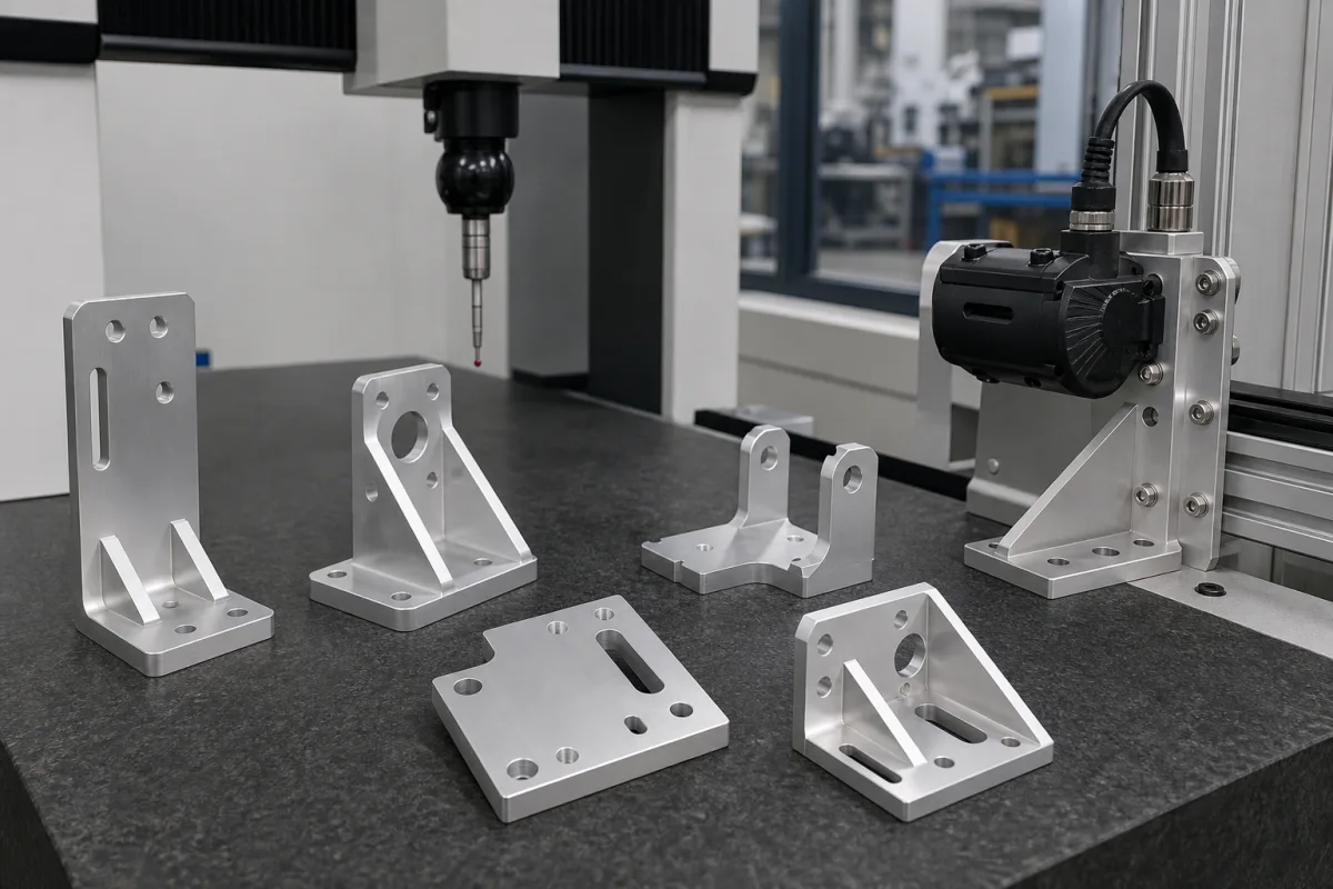
Aluminum mounting bracket, CNC-machined to hold motors, sensors and assemblies
CNC-machined aluminium brackets · datum faces and hole positions, tapped holes and inserts, contact with steel fasteners
An aluminium mounting bracket, in the sense used on this page, is a finished part machined from solid aluminium, plate or extruded angle, with flat mounting faces, located holes, slots, threaded holes and, where needed, stiffening ribs, that fixes a motor, sensor, camera, rail or other component in a precise position. Ask three things first: which faces and holes must be machined from one datum and to what tolerance, how threads in the aluminium will carry the bolt load, and what finish and fasteners keep it from corroding against steel.
Finished aluminium brackets machined to a drawing: L, U, angle, gusseted, motor, sensor, camera and rail brackets. Extruded aluminium profiles supplied as lengths, including T-slot framing, are covered on the Aluminum extrusion profile page. Die-cast and stamped steel brackets, and brackets in stainless or carbon steel, are outside this page except where compared.
CNFX editorial research · Sources checked October 12, 2026 · 3 sources
Machine the mounting faces and holes from one datum
Precimach, a machining supplier, lists L, U, angle, support, motor, sensor, camera, linear rail and robot mounting brackets, machined in aluminium 6061-T6, 6082-T6 and 7075-T6. It describes machining mounting faces, mounting holes and locating features from the same datum, completing key faces and holes in one setup where possible, using 5-axis machining for angled faces and multi-side holes, and checking hole positions, mounting faces and locating dimensions on a CMM before shipment. [1]
Shenzhen VMT lists its machined aluminium brackets in 6061-T6, 6063, 7075-T6, 2014, 2017 and 2011, with tolerances of ±0.01 mm for circularity and ±0.05 mm for planarity, citing ISO 4292:1985, and surface roughness from Ra 0.1 to 3.2. It lists clear, colour and hard anodizing among the finishes. [2]
Precimach states lead times of 7 to 15 working days and supply from one-piece prototypes to repeat production; for linear rail brackets it names flat mounting faces, hole spacing, parallelism and mounting-face height as the checked features. [1]
Editorial note: a published ±0.05 mm planarity is a supplier capability statement, not a guarantee for your part; put the datum scheme, flatness, perpendicularity and true position of the critical holes on the drawing and ask for a CMM report on first articles.
Give the supplier the drawing and 3D model with datums, the alloy and temper, quantity, critical tolerances (flatness, perpendicularity, hole positions), thread sizes and depths, any inserts, finish and colour, the mating fasteners, the load on the bracket, and the inspection report required.
02
Carry the bolt load in aluminium threads
NASA's Fastener Design Manual (Reference Publication 1228) gives the pullout load of a bolt in a tapped hole of a weaker material as the product of π, the pitch diameter, the thread engagement length and the material's shear stress, multiplied by an empirical factor of 1/3; the factor would be 1/2 if the threads were perfectly mated, and the lower value allows for thread mismatch. If the bolt's full strength is needed, the tapped depth is set from the weaker material. [3]
The same manual describes threaded inserts as giving a strong, wear-resistant tapped hole in soft materials, including nonferrous metals; their external thread is nominally 1/8 in. larger in diameter than the internal thread, so that a 10-32 bolt sits in the equivalent of a 5/16-18 thread. [3]
NASA's galvanic ranking lists aluminium 5056, 5052, 1100, 2024 and 7075 above mild steel and Type 304 and 316 stainless steel, and notes that the farther apart two materials are in the list, the greater the galvanic action between them. [3] Editorial note: a bracket that will be bolted with stainless fasteners in a wet place needs a finish and fastener choice agreed with the supplier, such as anodizing and isolating washers or coated fasteners.
03
Milled from solid, cut from plate or machined from extruded angle
Ask each supplier whether the bracket will be milled from solid, cut from plate or cut and machined from extruded angle, and which features are finished in one setup.
04
Plate, upright face, ribs and tapped holes on a machined bracket
Feature
Role
Fix in the order
Mounting plate
Flat face bolted to the frame; planarity ±0.05 mm listed. [2]
Flatness and datum.
Upright face
Carries the mounted part; perpendicular to base. [1]
Two build routes appear: CNC milling from 6061-T6, 6063, 6082-T6 or 7075-T6 stock, and aluminium extrusions cut and machined into brackets; anodizing is listed as a finish, and one maker names CMM inspection.
Precimach
Manufacturing site to be confirmed for the order
Lists CNC-machined L, U, angle, motor, sensor, camera and rail brackets in aluminium 6061-T6, 6082-T6 and 7075-T6, with CMM inspection.
Explore company information and manufacturing capabilities, then discuss the scope of your project with a relevant supplier.
Share this page
Compiled and source-reviewed by the CNFX editorial team.
Each manufacturer above links to the page on that company's own website where the product is listed, with the date we checked it. How we source and review
· Page last updated 13 October 2026
Buyer questions
Which aluminium alloys are used for machined brackets?
Suppliers list 6061-T6, 6082-T6 and 7075-T6, and also 6063, 2014, 2017 and 2011. [1][2]
How flat can a machined bracket face be?
One supplier lists ±0.05 mm planarity and ±0.01 mm circularity; put your own values on the drawing. [2]
Are threads in aluminium strong enough?
NASA's manual sets tapped depth from the weaker material and describes threaded inserts for soft materials. [3]
Sources and what still needs a direct check
Sources checked 2026-10-12. NASA's Fastener Design Manual is a government engineering reference; Precimach and Shenzhen VMT are machining suppliers describing their own bracket work.