Thermal management · Thermal resistance, airflow and interface
A heat sink is chosen by thermal resistance, not by size. Work out what the device can tolerate, take away what the device and interface already use, and pick a heat sink whose resistance at your real airflow is lower than what remains.
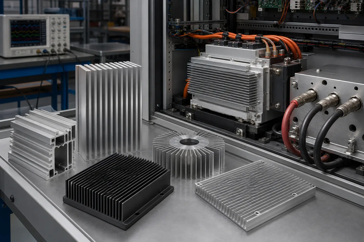
Extruded, die-cast, skived and machined aluminium heat sinks for power electronics, LEDs and electronic devices, cooled by natural or forced air. Liquid cold plates and heat pipes are mentioned only where suppliers list them.
CNFX editorial research · Sources checked October 11, 2026 · 4 sources
Aavid Thermalloy's selection guide starts from four facts: the heat Q the device generates, its maximum junction temperature Tj, the maximum ambient air temperature Ta, and whether cooling is natural or forced (with air velocity). Total resistance is θja = θjc + θcs + θsa, and the heat sink must provide θsa = (Tj − Ta) / Q − (θjc + θcs). [1]
Aavid's worked example: a TO-220 device dissipating 13 W with Tj max 150 °C, Ta max 50 °C, θjc 3.0 °C/W and an interface pad giving θcs 0.5 °C/W needs θsa no higher than about 4.2 °C/W; a heat sink rated 4.0 °C/W at 400 ft/min meets it. [1]
Only θcs and θsa are under the designer's control; θjc comes from the device data sheet. [1]
Give the supplier the device and its losses, maximum junction temperature and θjc, the maximum ambient air temperature at the heat sink, the airflow (natural or fan, with velocity), and the space envelope.
02
Use the curve for your airflow
Aavid explains that catalogue graphs give two readings: in natural convection, temperature rise against watts; in forced convection, thermal resistance against air velocity. Its example heat sink rises 75 °C at 3 W in natural convection (25 °C/W) but only 28.5 °C at 400 ft/min (9.5 °C/W). Fan free-air ratings should be derated by 60–80% for back pressure when estimating velocity. [1]
Electronics Cooling explains that in open, unducted layouts air escapes the fin field early (bypass), reducing performance, and that a heat sink larger than the heat source adds spreading resistance. Its point: ask what junction temperature you need, not how many watts a heat sink can take. [2]
Ask the supplier for performance at your airflow and orientation, measured or simulated with your heat-source footprint.
03
Choose the interface and the finish
Aavid gives θcs = ρ·t / A: interface resistance rises with the material's thermal resistivity and thickness and falls with contact area. Its table lists resistivity (°C·in/W) of 0.17 for 6000-series aluminium, 0.10 for copper, 5.6 for an anodised finish, 204 for silicone grease and 1,200 for dead air; grease is used because it fills voids that metal-to-metal contact leaves. [1]
So flatness and surface finish at the mounting area matter, and an anodised layer under the device adds resistance. Specify flatness, roughness and whether the mounting pad is left bare, along with the interface material and screw torque.
04
Extruded 6063-T5, skived, die-cast and heat-pipe heat sinks on supplier pages
BY Thermal lists extruded heat sinks in 6063-T5 alongside skived heat sinks, heat-pipe heat sinks and liquid cold plates; Kingrun lists die-cast aluminium heat sinks such as one for an EV traction motor controller; Sinoextrud, Wellste, Shengxin, CHAL, HTS and Shenghai list extruded aluminium heat sinks among profiles; Ecotherm lists custom high-power heat sinks. Ask each for thermal data, not only dimensions. [3][4]
05
Base, fins, mounting pad, finish and fan or duct
The mounting pad and finish set θcs and the fins with their airflow set θsa, the two resistances Aavid says the designer controls; Electronics Cooling adds spreading resistance in a base larger than the heat source. [1][2]
Feature
Role
Fix in the order
Base
Spreads heat from the device; spreading resistance if larger than source. [2]
Base, fin geometry, finish and θsa at your airflow for a heat sink quotation
The thermal-resistance row is the acceptance test: Aavid's TO-220 example needs about 4.2 °C/W, and for your own device the supplier's curve at your airflow and orientation has to fall below the value worked out above. [1]
Paste it into your enquiry below or into an email to a maker, then replace every bracket.
Device: [type and package; power dissipated; Tj max; θjc; number of devices and positions]
Ambient: [maximum air temperature at the heat sink; enclosure or open]
Airflow: [natural convection or fan; air velocity; direction; ducting]
Interface: [pad or grease; thickness; screw torque]
Geometry: [space envelope; mounting holes; orientation]
Material and finish: [alloy; anodised or bare; masked areas]
Documents: [thermal curve or simulation at your conditions; drawing; sample]
12 companies list this product among what they make. Company figures are quoted from each
company's own website; every card states where the relationship came from.
BY Thermal
Manufacturing site to be confirmed for the order
Lists extruded, skived and heat-pipe heat sinks and liquid cold plates.
Explore company information and manufacturing capabilities, then discuss the scope of your project with a relevant supplier.
Share this page
Compiled and source-reviewed by the CNFX editorial team.
Each manufacturer above links to the page on that company's own website where the product is listed, with the date we checked it. How we source and review
· Page last updated 13 October 2026
Buyer questions
How do I calculate the heat sink thermal resistance I need?
θsa = (Tj − Ta) / Q − (θjc + θcs). For 13 W, Tj 150 °C, Ta 50 °C, θjc 3.0 and θcs 0.5 °C/W, that is about 4.2 °C/W. [1]
How much does a fan help a heat sink?
In Aavid's example a heat sink with 25 °C/W in natural convection drops to 9.5 °C/W at 400 ft/min; derate fan free-air flow for back pressure. [1]
Why use thermal grease?
It fills microscopic voids between device and heat sink that would otherwise hold air, which has very high thermal resistivity. [1]
Sources and what still needs a direct check
Sources checked 2026-10-11. Aavid Thermalloy (now Boyd) is a heat sink manufacturer; its selection guide gives the thermal resistance method. Electronics Cooling is a trade publication on thermal management. Supplier pages describe their own offers.