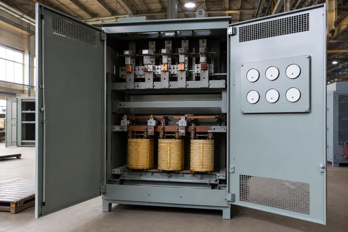
Voltage control unit for dielectric strength testers: rate-of-rise control, step-by-step schedules and breakdown cut-off on the regulator side
The part of a dielectric strength tester that raises the test voltage and stops it · motor-driven regulators ramping from 1 V/s to 2,000 V/s, the 500 V/s short-time test and its step-by-step schedule, and how the primary circuit is limited and cut when the specimen breaks down
A dielectric strength test is defined less by its maximum voltage than by how the voltage gets there: a uniform rise at a stated rate, or a staircase of steps held for a set time, ending the moment the insulation fails. The high-voltage transformer only multiplies what it is given. The voltage control unit on its primary side, a motor-driven variable autotransformer, a stepping drive or an electronic amplifier with its controller, decides the rate, the steps and the cut-off.
Voltage control units on the low-voltage side of AC dielectric strength and withstand testers: motor-driven variable autotransformers and their drives, rate-of-rise and step-schedule controllers, primary-side current limiting and breakdown cut-off, and electronic (PWM amplifier) replacements for the autotransformer. Complete AC and DC hipot testers, with test voltage, duration and leakage limits, are covered on the Dielectric strength (hipot) tester page; AC test transformers and complete AC dielectric test sets, sized by voltage, current and kVA, on the High-voltage test transformer page; portable DC withstand and leakage-current test sets on the High-voltage generator for DC withstand and leakage-current testing page; tap changers for power transformers on the Tap changers page.
CNFX editorial research · Sources checked October 12, 2026 · 4 sources
Rate of rise from 1 V/s to 2,000 V/s: what a motor on the regulator has to do
The Western Region Industrial Research Center of Hiroshima Prefecture had a withstand tester with no ramp function and added one: a bipolar stepping motor coupled to the shaft of the tester's voltage-setting knob, run by an Arduino. On the 0–5 kV range, 180° of rotation took the output to 3.4 kV, so the ramp rate is set by the motor speed: [1]
The error between target and achieved rate was at most 1 % over the range used. Because the motor moves in steps, the rise still showed some unevenness; the centre plans a five-phase motor with a smaller step angle to keep within the ±0.3 % input-voltage variation of the existing tester. The tester itself stops applying voltage and sounds a buzzer when a preset leakage current is detected, and the add-on stops the motor when a sound sensor hears that buzzer. [1] Editorial calculation: 3.4 kV in 6.8 s is 500 V/s, so the same drive would need 60 s to take a 30 kV range to full output at that rate.
Hubbell's patent on DC hipot testers notes that insulation breakdown testers have used a line-frequency (50/60 Hz) variable autotransformer to raise and lower the voltage, which it calls disadvantageous where output voltage and performance need to be monitored or adjusted; it replaces the autotransformer with a PWM amplifier whose output is raised at a set ramp rate in volts per second, monitoring leakage current and voltage as it goes. [4]
Specify the rates the control unit must produce, their tolerance, and whether the ramp comes from a motor-driven autotransformer or an electronic source.
02
Short-time and step-by-step programmes: 500 V/s, then 40 % and fixed increments held one minute
A 1952 patent, US 2,724,087, automates a power-driven autotransformer for the two test programmes then run on insulating materials, which it says needed two people when done by hand, one reading the meter and one turning the voltage, without a uniform rate. [2]
The patent's controller uses a timing element, a meter with control contacts spaced to the schedule, and an element that stops the test when the specimen fails; a clutch with a heavy-duty solenoid separates the motor from the autotransformer quickly at each step, and the patent warns that if the timing disc lags, the voltage can rise two steps at once. [2] The Hiroshima retrofit likewise runs staged rises and a change of rate after a set voltage. [1]
Programme in the patent
Control the unit must provide
Short-time test
Raise from zero uniformly to breakdown at 500 V/s, or a lesser rate if breakdown comes too soon [2]
Step-by-step test, start
Apply 40 % of the short-time breakdown voltage [2]
Step-by-step test, increments
0.5 kV up to 12.5 kV short-time breakdown, 1.0 kV for 12.5–25 kV, 2.5 kV for 25–50 kV [2]
Step-by-step test, timing
Hold each step one minute; change to the next step within 10 seconds [2]
List each programme the unit must run: rates, starting voltage, step size, hold time and transition time.
03
At breakdown: at least 20 mA of short-circuit current above 15 kV, then the primary is cut
Baur Prüf- und Messtechnik's patent US 4,663,585 deals with the current that flows when the specimen punctures. It cites testing specifications such as VDE 0370 that require at least 20 mA of short-circuit current at the spark gap for voltages above 15 kV, while too high a current at high test voltages is also to be avoided. [3]
Its solution sits in the primary of the variable-voltage transformer: resistors in the primary lead are bypassed by switches at low voltage and switched into circuit one after another as the test voltage rises, so the transformer's internal resistance increases in steps toward the breakdown range. An alternative uses a power semiconductor whose forward resistance is controlled by the primary or secondary voltage. When breakdown current flows in the secondary, the voltage across a resistor in the secondary winding triggers interruption of the primary supply. [3]
Editorial note: three separate quantities meet here, and a specification should state each one: the minimum short-circuit current the test standard requires, the leakage-current trip setting, and how fast the primary is interrupted after breakdown. [3][1]
State the minimum short-circuit current, the leakage or breakdown trip setting and range, and how the unit records the breakdown voltage.
04
What to send when specifying a tester's voltage control unit
Paste it into your enquiry below or into an email to a maker, then replace every bracket.
Tester: [maximum test voltage; ranges; AC or DC; test transformer ratio and kVA]
Control element: [motor-driven autotransformer / electronic amplifier]
Programmes: [rates of rise; step size; hold time; transition time]
Accuracy: [rate tolerance; output stability]
Breakdown: [minimum short-circuit current; trip current setting; cut-off method]
Interfaces: [remote control; data logging of breakdown voltage]
Explore company information and manufacturing capabilities, then discuss the scope of your project with a relevant supplier.
Share this page
Compiled and source-reviewed by the CNFX editorial team.
Each manufacturer above links to the page on that company's own website where the product is listed, with the date we checked it. How we source and review
· Page last updated 13 October 2026
Buyer questions
How is the rate of voltage rise set on a dielectric tester?
By the speed of the drive on the regulator: one retrofit turned a tester's voltage knob with a stepper motor and reproduced 1 V/s to 2,000 V/s within 1 %. [1]
What is the step-by-step dielectric test schedule?
In US 2,724,087: start at 40 % of short-time breakdown, step 0.5, 1.0 or 2.5 kV depending on that breakdown, hold each step one minute, change within 10 seconds. [2]
How much current must a tester supply at breakdown?
Baur's patent cites specifications such as VDE 0370 requiring at least 20 mA short-circuit current above 15 kV. [3]
Can an electronic source replace the variable autotransformer?
Hubbell's DC hipot patent replaces it with a PWM amplifier ramped at a set rate in volts per second. [4]
Sources and what still needs a direct check
Sources checked 2026-10-12. Ramp control results come from a 2024 report by Hiroshima Prefecture's Western Region Industrial Research Center; test programmes from US patent 2,724,087; breakdown current limiting and cut-off from a Baur Prüf- und Messtechnik patent; the electronic alternative from a Hubbell patent.