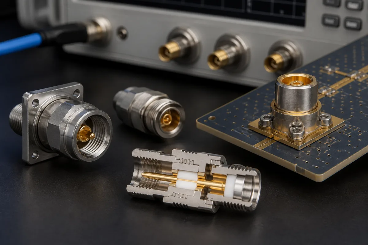
RF and microwave · Connector type by frequency, mode cut-off, intermating, torque and connector care
A high-frequency RF connector joins coaxial cables, boards and instruments while keeping a controlled 50 Ω coaxial path up to its frequency limit. Ask three things first: the highest frequency and the connector series it implies, what it must mate with, and the performance data (VSWR, insertion loss, mating cycles) and torque the supplier specifies.
Coaxial RF and microwave connectors and adapters: N, SMA, 3.5 mm, 2.92 mm, 2.4 mm, 1.85 mm and 1.0 mm series, cable, panel and PCB types. Fibre-optic connectors, power and data connectors, and complete RF cable assemblies sold as systems are outside this page.
CNFX editorial research · Sources checked October 12, 2026 · 4 sources
Rohde & Schwarz's coaxial connector handling note lists maximum frequencies of 11 GHz for normal and 18 GHz for precision Type N (4 GHz for 75 Ω N), 12 GHz for SMA with some versions to 18 GHz, 26.5 GHz for precision 3.5 mm, 40 GHz for 2.92 mm, 50 GHz for 2.4 mm, 67 GHz for 1.85 mm and 110 GHz for 1.0 mm. The 3.5 mm and 2.92 mm types mate mechanically with SMA, though some male SMA pins can damage 3.5 mm connectors; 2.4 mm and 1.85 mm do not interface with SMA, 3.5 mm or 2.92 mm. It advises not connecting precision and low-cost connectors together. [1]
The note gives the coaxial impedance Z₀ ≈ (138 Ω ÷ √εr) × log₁₀(D ÷ d) and the TE11 mode cut-off fc ≈ c ÷ (π × (D + d) ÷ 2 × √εr), with the usable limit about 90–95% of fc. For an air-filled 3.5 mm connector with d = 1.52 mm and D = 3.5 mm it gives about 38 GHz, adding that some makers rate 3.5 mm to 33 GHz. [1]
Editorial calculation: 138 × log₁₀(3.5 ÷ 1.52) ≈ 50.0 Ω, and 3 × 10⁸ ÷ (π × 2.51 mm) ≈ 38.0 GHz, so 90–95% gives about 34–36 GHz. [1] Smaller connectors reach higher frequencies, which is why the series step down in size.
A connector maker's product specification shows the figures to request for one part. Samtec's 2.92 mm PCB edge-launch jack (revision A, March 2025) gives 50 Ω, DC to 40 GHz, VSWR 1.10 (typ.) to 18 GHz and 1.15 (typ.) from 18 to 40 GHz on its own test board, insertion loss at most 0.035 × √f(GHz) dB, contact resistance below 6.0 mΩ (centre) and 2.0 mΩ (outer), dielectric withstanding voltage 500 V RMS minimum, insulation resistance 5,000 MΩ minimum and a 170 V RMS rating at sea level, the voltage figures possibly limited further by PCB design. [3] Mechanically it states an IEEE Std 287 interface, 0.9–1.13 N·m mating torque, 500 cycles minimum durability, 17.8 N centre-contact retention, −65 to +165 °C, and MIL-STD-202 thermal shock, vibration (20 g) and mechanical shock (100 g) tests. Materials are a passivated stainless steel body, beryllium-copper centre contact with 50 µin gold over nickel, and PTFE and Ultem dielectrics. [3]
Editorial calculation: at 40 GHz the formula gives 0.035 × √40 ≈ 0.22 dB per connector, and VSWR 1.15 corresponds to a return loss of about 23 dB. [3]
Give the supplier the frequency range, connector series and gender, cable type or PCB launch, impedance, VSWR and insertion loss limits, mating cycles, power, environment, materials and plating, and inspection or test reports required.
02
Mate, torque and look after the connectors
Rohde & Schwarz gives torque limits of 1.5 N·m (13.3 lb-in) for Type N and ruggedized connectors, 0.56 N·m (5 lb-in) for SMA, 0.9 N·m (8 lb-in) for 3.5, 2.92, 2.4 and 1.85 mm, and 0.34 N·m (3 lb-in) for 1.0 mm, noting that other makers' limits must come from the maker and that when mating 3.5 mm to SMA the lower limit applies. [1]
Its handling rules: inspect before mating and discard damaged connectors, keep them clean and capped, align both connectors on the same axis, turn only the coupling nut and never rotate one connector against the other, finger-tighten to within about half a turn before using a calibrated torque wrench, and stop when the wrench breaks. Resistance before that point suggests damage. Connector savers protect expensive instrument ports. [1] Keysight's help adds that ESD can damage instrument inputs and recommends connector savers and holding open-ended wrenches on the flats to stop rotation. [2]
Torque and mating life also depend on the connector body material, so state it in the order. Rosenberger's SMA series page gives 50 Ω, an interface to IEC 60169-15, EN 122110 and MIL-STD-348A Fig. 310, DC to 18 GHz and a return loss of ≥ 30 dB (typ.) for a straight cable connector. [4] It lists ≥ 500 mating cycles for CuBe or stainless steel against ≥ 100 for CuZn (brass), a coupling test torque of ≥ 1.7 N·m (CuBe/stainless) or ≥ 0.6 N·m (CuZn), and a recommended coupling torque of 0.8 to 1.1 N·m (CuBe/stainless) or ≥ 0.5 N·m (CuZn). [4]
Editorial calculation: Rosenberger's recommended 0.8–1.1 N·m for stainless SMA is higher than the 0.56 N·m Rohde & Schwarz gives for SMA, so agree the torque wrench setting with the connector maker, and use the lower figure when an SMA mates with a 3.5 mm or 2.92 mm port. A 30 dB return loss corresponds to a reflection coefficient of 10^(−30/20) ≈ 0.032 and a VSWR of (1 + 0.032) ÷ (1 − 0.032) ≈ 1.07. [4][1]
03
Millimetre-wave series, SMA and N types on the supplier list
MetabeeAI lists 1.0, 1.85, 2.4, 2.92 and 3.5 mm connectors with adapters and test cables; Huajian lists 2.92 mm, N, SMA and 4.3-10 connectors with cable assemblies; Jinbeili lists SMA, SMB and MCX connectors; Topwave and Maniron list RF coaxial connectors with dividers, couplers and filters; Daytai and Fleconn list RF coaxial connectors within wider cable and connector ranges.
Silver or gold in the R&S note; e.g. 50 µin gold over nickel on one centre contact. [1][3]
Plating and thickness.
Coupling nut and body material
Sets mating life and torque: CuBe/stainless ≥ 500 cycles, CuZn ≥ 100 in one SMA series. [4]
Material; recommended torque.
05
Frequency, VSWR and mating life to state for each connector
Pick the frequency row first, since it fixes the series; the body-material row then decides how many mating cycles and how much torque the connector is rated for. [1][4]
MetabeeAI lists the 1.0 to 3.5 mm precision series with adapters and test cables; the other cards list SMA, N, SMB, MCX or general RF coaxial connectors.
MetabeeAI
Manufacturing site to be confirmed for the order
Lists 1.0, 1.85, 2.4, 2.92 and 3.5 mm connectors, adapters and test cables.
Explore company information and manufacturing capabilities, then discuss the scope of your project with a relevant supplier.
Share this page
Compiled and source-reviewed by the CNFX editorial team.
Each manufacturer above links to the page on that company's own website where the product is listed, with the date we checked it. How we source and review
· Page last updated 13 October 2026
Buyer questions
Can I mate SMA with 3.5 mm or 2.92 mm connectors?
Mechanically yes, but some SMA male pins can damage 3.5 mm connectors; use the lower torque limit of the two. [1]
Which connector do I need for 40 GHz?
Rohde & Schwarz lists 2.92 mm to 40 GHz; 2.4 mm reaches 50 GHz and 1.85 mm 67 GHz. [1]
How tight should an SMA connector be?
0.56 N·m (5 lb-in) in Rohde & Schwarz's table; 3.5 mm and 2.92 mm are 0.9 N·m. [1]
What does a 2.92 mm connector datasheet state?
One maker's PCB jack gives DC to 40 GHz, VSWR 1.10–1.15 (typ.), insertion loss ≤0.035 × √f dB, 500 mating cycles and 5,000 MΩ insulation resistance. [3]
Does connector material affect SMA mating life?
Rosenberger lists ≥ 500 mating cycles for CuBe or stainless steel SMA connectors and ≥ 100 for CuZn (brass), with different recommended torques. [4]
Sources and what still needs a direct check
Sources checked 2026-10-12. Rohde & Schwarz and Keysight are test-equipment makers; their connector handling guidance is their own. Samtec and Rosenberger publish data for their own connectors.