Editorial Technical Reference

High-Pressure Ammonia Flow Control Valve

This page explains how High-Pressure Ammonia Flow Control Valve is classified within Fertilizers and Nitrogen Compounds Manufacturing. Technical values and manufacturer relationships are research references; confirm the current specification and supplier evidence for each order.

Technical Definition & Core Assembly

This industrial valve is engineered for precise regulation of high-pressure ammonia flow within fertilizer manufacturing processes, specifically in the production of nitrogen compounds.
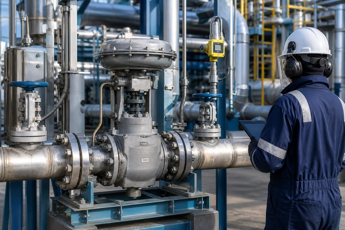
Representative product image. Confirm appearance and specifications with the manufacturer.

Product Specifications

Technical details and manufacturing context for High-Pressure Ammonia Flow Control Valve

Definition
This industrial valve is engineered for precise regulation of high-pressure ammonia flow within fertilizer manufacturing processes, specifically in the production of nitrogen compounds. It is a critical component in synthesis loops, where accurate dosing of ammonia into reaction vessels is essential for optimizing efficiency and preventing process upsets. The valve maintains stable pressure conditions, ensuring reliable operation in corrosive ammonia environments. Its robust construction, featuring a stainless steel body and PTFE seals, is designed to withstand the demanding conditions of ammonia service. The valve operates on a quarter-turn principle, with a hardened chrome steel ball that rotates to control flow. When the ball's through-hole aligns with the pipeline, maximum flow is achieved; rotating it 90 degrees blocks flow completely, and intermediate positions provide proportional control. This design allows for fine adjustment of flow rates, contributing to precise process control. The valve is available in various configurations to suit different system requirements, with port sizes ranging from DN15 to DN100 and flow coefficients (Cv) from 0.1 to 40. It is rated for working pressures up to 1.6 bar and operates within a temperature range of -40°C to 85°C. The valve offers a control precision of ±0.5% and a response time of ≤1 second, making it suitable for dynamic process control. It can be equipped with an electric actuator requiring a 24 V DC supply and a 4-20 mA control signal. The enclosure rating is IP65 to IP67, providing protection against dust and water ingress. For verification, the valve's leakage class is rated IV to VI per ANSI/FCI 70-2, and its body material is CF8M stainless steel (ASTM A351). The seat material is PTFE (ASTM D4894), ensuring chemical compatibility with ammonia. The required actuator torque ranges from 50 to 200 Nm, and the valve weight varies from 5 to 30 kg depending on size and actuator. All specifications are reference values and must be confirmed with the manufacturer for specific models and applications.
Working Principle
The valve uses a rotating ball with a through-hole to regulate flow. When the hole is aligned with the pipeline, flow is at maximum; when rotated 90 degrees, flow is completely blocked. Intermediate positions provide proportional flow control, allowing precise adjustment of ammonia flow rates. The ball is actuated by a quarter-turn mechanism, either manually or via an electric actuator, which receives a 4-20 mA control signal. The valve's design ensures tight shut-off and accurate flow regulation, with a control precision of ±0.5% and a response time of ≤1 second. The PTFE seat provides a reliable seal, and the hardened chrome steel ball resists wear in abrasive ammonia service.
Common Materials
Stainless Steel 316L, PTFE Seals, Hardened Chrome Steel Ball
Technical Parameters
ParameterTypical rangeNotes & selection driver
Pressure RatingRequired1.0–1.6 barMaximum working pressureISO 5208
Temperature RangeRequired-40–85 °COperating temperature limits
Flow CoefficientRequired0.1–40 CvValve flow capacityIEC 60534
Port SizeRequiredDN15–DN100 inchesConnection port diameterISO 7005
Leakage ClassRequiredIV–VI ANSI/FCI 70-2Seat leakage ratingIEC 60534-4
Actuator Torque50–200 NmRequired operating torque
Control Precision±0.5 %Ensures accurate flow regulationIEC 60534-4
Response Time≤1 sFast response for process control
Supply Voltage24 ±10% V DCFor electric actuatorIEC 61131-2
Control Signal4–20 mAStandard analog inputIEC 60381
Enclosure RatingIP65–IP67Protects against dust and waterIEC 60529
Body MaterialCF8MCorrosion-resistant stainless steelASTM A351
Seat MaterialPTFEChemical compatibility with ammoniaASTM D4894
Weight5–30 kgDepends on size and actuator

Ranges are indicative industry figures for RFQ preparation, not a supplier commitment. Confirm every value and standard with the legal manufacturer before ordering.

Components / BOM
  • Valve Body Part
    Main pressure-containing structure
    Material: Stainless Steel 316L
  • Ball Part
    Rotating element for flow control
    Material: Hardened Chrome Steel
  • Seat Rings Part
    Provide sealing between ball and body
    Material: Reinforced PTFE
  • Stem Part
    Transmits torque from actuator to ball
    Material: Stainless Steel 316
  • Actuator Mounting Pad Optional Part
    Interface for actuator installation
    Material: Carbon Steel
  • Electric Actuator Optional
    Turns the ball to the commanded position from a 4-20 mA signal.
  • Stem Seal
    Seals where the stem passes out of the body, keeping ammonia from leaking to atmosphere.

Industry Taxonomies & Aliases

Commonly used trade names and technical identifiers for High-Pressure Ammonia Flow Control Valve.

Industrial Ecosystem & Supply Chain Structure

Complementary Systems
Downstream Applications
Specialized Tooling

Application Fit & Sizing Matrix

Operational Limits
pressure: Up to 300 bar (4350 psi)
flow rate: 0.5 to 500 m³/h (depending on valve size)
temperature: -40°C to 150°C
slurry concentration: Up to 30% solids by weight (with hardened trim)
Media Compatibility
✓ Anhydrous ammonia ✓ Ammonia-water solutions ✓ Ammonium nitrate solutions
Unsuitable: Chlorinated hydrocarbons (risk of stress corrosion cracking)
Sizing Data Required
  • Required flow rate (m³/h)
  • Upstream pressure (bar)
  • Required pressure drop (bar)

Reliability & Engineering Risk Analysis

Failure Mode & Root Cause
Cavitation damage
Cause: Pressure drop across valve trim causing vapor bubble formation and implosion, leading to pitting and erosion of valve components, especially in high-pressure ammonia service where fluid properties exacerbate this effect.
Stem packing leakage
Cause: Degradation of packing material due to ammonia's chemical attack and thermal cycling, combined with inadequate maintenance of packing gland compression, resulting in hazardous ammonia release.
Maintenance Indicators
  • Audible hissing or whistling from valve body or stem area indicating ammonia leakage
  • Visible frosting or ice formation on valve exterior due to ammonia expansion and cooling during leakage
Engineering Tips
  • Implement regular ultrasonic flow monitoring to detect cavitation onset before physical damage occurs, allowing for trim adjustment or pressure modification
  • Use ammonia-compatible materials (like stainless steel trim and specialized packing) and establish quarterly packing gland adjustment schedule with torque specifications

Indicative industry ranges for design and RFQ preparation. Confirm the exact figures and applicable standard with the manufacturer before specifying.

Compliance & Manufacturing Standards

Applicable Standards
ISO 5208:2015 Industrial valves - Pressure testing of valves ANSI/FCI 70-2 Control Valve Seat Leakage DIN EN 12516-1 Industrial valves - Shell design strength - Part 1: Tabulation method for steel valve shells

Quoted from the published standard.

Manufacturing Precision
  • Bore diameter: +/-0.025mm
  • Seat flatness: 0.05mm
Quality Inspection
  • Hydrostatic pressure test (to 1.5x rated pressure)
  • Helium leak test for ammonia compatibility

Manufacturers of High-Pressure Ammonia Flow Control Valve

Manufacturer profiles associated with High-Pressure Ammonia Flow Control Valve.

Sourcing High-Pressure Ammonia Flow Control Valve from China?
Tell us your specification and target quantity — we will match it against manufacturer records and come back with the factories that fit.
Request manufacturers We manufacture this

Manufacturer listings support early research and capability understanding. They are not certification, ranking, or transaction guarantees.

Technical documentation
Request current drawings, revision history, and a signed specification sheet.
Manufacturing capability
Verify equipment lists, process limits, capacity, and representative production evidence.
Inspection readiness
Confirm test methods, calibrated equipment, sampling plans, and traceable reports.
Supplier transparency
Check the legal entity, factory address, ownership, certifications, and direct contacts.

CNFX does not score or rank suppliers. Buyers must verify all claims and documents with the legal manufacturer before ordering.

Frequently Asked Questions

What is the maximum working pressure of this valve?

The pressure rating is listed as 1.0–1.6 bar. However, this is a reference range; the actual maximum working pressure depends on the specific valve model, size, and materials. Always verify with the manufacturer for your application.

What materials are used in the valve construction?

The body is made of CF8M stainless steel (ASTM A351), the ball is hardened chrome steel, and the seals are PTFE. These materials are selected for corrosion resistance and chemical compatibility with ammonia. Confirm material grades with the manufacturer for your specific requirements.

How does the valve achieve precise flow control?

The valve uses a quarter-turn ball with a through-hole. By rotating the ball to intermediate positions, the flow area is adjusted, providing proportional control. The valve offers a control precision of ±0.5% and a response time of ≤1 second, enabling accurate regulation in dynamic processes.

What are the electrical requirements for the actuator?

The electric actuator requires a 24 V DC supply (with ±10% tolerance) and a 4-20 mA control signal. The enclosure rating is IP65 to IP67. These specifications are reference values; verify the actuator's exact requirements with the manufacturer.

Data Basis

Editorial classification, named public sources where available, and source-reviewed manufacturer records.

Preliminary Technical Classification
This page supports structured research, RFQ preparation, and supplier evaluation. It does not replace buyer-led supplier qualification, standards review, or technical approval.
Buyer enquiry

Request manufacturing insight for High-Pressure Ammonia Flow Control Valve

Ask for use case, specification boundaries, supplier type, and RFQ preparation information for this product.

Where it goes
Straight to the CNFX editorial desk, and to the manufacturer if this product is linked to a claimed profile. Nothing is broadcast to a supplier list.
Your details stay here
We do not sell or rent enquiry data, and we do not add you to a mailing list. Used only to answer this request.
No commission, no middleman
CNFX is a directory. We take no cut of any order and never negotiate on a supplier's behalf.
What we don't claim
A listing is not an endorsement. Qualify every supplier and verify every figure yourself before ordering.

Your business information is used only to process this request.

Thank you! Your message has been sent. We'll respond within 1–3 business days.
Sorry, we couldn't send your message. Please try again, or email us at contact@cnfx.com.

Need to Manufacture High-Pressure Ammonia Flow Control Valve?

Compare manufacturer profiles with relevant product and process capability.

First Product
Next Product
High-Pressure Ammonia Synthesis Loop Heat Exchanger Tube Bundle
Get QuotesChat